PCL5100 MOTHERBOARD Pentium® and Pentium®MMX processor ready USER GUIDE Intel and Pentium® and Pentium®MMX are registered trademarks of Intel Corporation. Information contained in this document is subject to change without notice and does not represent a commitment on the part of Mitsubishi Electric. http://www.mitsubishi-computers.
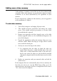
FEATURES AND UPGRADES This chapter describes the features of the PCL5100 motherboard and gives step-by-step instructions for adding more system or video memory, upgrading the processor, and replacing the configuration battery. Details of all relevant motherboard connectors and jumper settings are included. This motherboard and all its components extremely sensitive to static electricity.
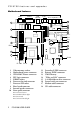
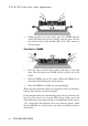
PCL5100 features and upgrades Motherboard features Parallel Video USB (optional) Com 1 Mouse Key/Bd Out In 18 1 17 16 2 15 14 PL11 3 PL4 PL3 13 4 12 PL19 11 5 6 PL201 PL 202 1 2 3 4 5 6 7 8 9 10 PL 18 Video memory sockets Motherboard power connector VESA/AMC feature connector PSU logic connector DIMM sockets Processor fan-sink connector Processor ZIF socket Riser board connector Internal speaker connector Front panel connector Pins 1-2 Power button Pins 3-4 HD indicator light Pins 5-6 Unus
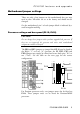
PCL5100 features and upgrades Motherboard jumper settings There are only a few jumpers on the motherboard that you may need to alter. All others are set at the factory and should not be changed. On the motherboard, pin 1 of each jumper block is indicated by a small triangular marking. Processor voltage and bus speed (PL19, PL18) CAUTION Do not change these jumpers unless you have upgraded the processor. If they are set incorrectly the processor and other vital motherboard components could be destroyed.
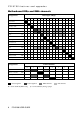
PCL5100 features and upgrades Processor Speed Jumper block PL19 BF1 BF0 FS PW2 PW1 PW0 Pentium Pentium Pentium Pentium Pentium Pentium Pentium Pentium/MMX Pentium/MMX Pentium/MMX 90 MHz 100 MHz 120 MHz 133 MHz 150 MHz 166 MHz 200 MHz 166 MHz 200 MHz 233 MHz High High High High Low Low Low Low Low High High High Low Low Low Low High Low High High In Out In Out In Out Out Out Out Out In In In In In In In Out Out Out In In In In In In In Out Out Out In In In In In In In Out Out Out On-board video
PCL5100 features and upgrades BIOS upgrade and recovery (PL11, PL3) These jumpers should not normally be changed except by a service engineer or at the direction of a service engineer. CMOS is cleared by moving the PL11 jumper to the 2-3 position for a few moments while the system is turned off, then returning it to the normal 1-2 position.
PCL5100 features and upgrades Motherboard IRQs and DMA channels Components Interrupts (IRQs) 0 1 2 3 4 5 6 7 8 9 10 11 12 13 14 15 System timer Keyboard controller PIC daisy chain Serial port 2 BS Serial port 1 BS Audio JS Diskette controller BS Parallel port BS Real time clock On-board video JS USB BS Mouse BS Co-processor Primary E-IDE BS Secondary E-IDE BS Components DMA channels 0 Audio JS Diskette controller BS Parallel port (ECP) BS 1 2 3 4 5 6 DMAC
PCL5100 features and upgrades Adding more memory You can give your PC more memory by adding or replacing memory modules called “DIMMs”. The motherboard’s two DIMM sockets accept DIMMs of up to 128 Mbytes in any combination (giving a maximum memory capacity of 256 Mbytes). IMPORTANT The DIMMs you use must have the following specification: gold contacts, 3.3V, 64-bit, unbuffered, either SDRAM-type with Serial Presence Detect (SPD) and a CAS latency of 2 at 66 MHz or else EDO-type with 60 ns timing.
PCL5100 features and upgrades 3. Pushing gently on its top corners, press the DIMM into the socket and make sure the two end clips snap into place. Do not use excessive force. If the module will not fit easily, remove it and start again. To remove a DIMM 1. Press the tabs on both of the socket’s end clips at the same time. This will release the DIMM and lift it partly out of the socket. 2. Pull the DIMM clear of the socket. Hold the DIMM by its ends and avoid touching the metal contacts. 3.
PCL5100 features and upgrades Adding more video memory Video memory is memory reserved for use by the on-board video controller. More video memory can provide more colours or higher resolutions to an extent determined by the capabilities of your monitor. If your computer has 1 Mbyte of video memory, you can upgrade it to the maximum of 2 Mbytes. To add video memory 1. Turn off the computer and unplug all power cords. 2. Take suitable anti-static precautions and remove the system covers.
PCL5100 features and upgrades Upgrading the processor The ZIF socket is designed to accept Pentium® processors (see the table earlier in this chapter). You may wish to upgrade your processor by replacing it with one of higher performance. Read the following instructions carefully before starting work. Changing the processor 1. Turn off the computer and unplug all power cords. 2. Take suitable anti-static precautions and remove the system covers.
PCL5100 features and upgrades 10. Separate the fan-sink from the processor by twisting the fansink from side to side to loosen the grip of the thermal bonding compound, then slide the fan-sink off to one side of the processor. WARNING When you remove the fan-sink there will be a residual deposit of thermal bonding compound on the bottom of the fan-sink and the top of the processor. This compound can cause skin irritation and stain clothing. Avoid prolonged or repeated contact with skin.
PCL5100 features and upgrades 15. Move the securing lever to the locked position. Apply just enough pressure to overcome the resistance offered by the lever. 16. Reposition the fan-sink on top of the new processor. ◊ You may have either of two different types of fan-sink. Note that the larger fan-sink overhangs the socket at one side. 1 2 1 2 17. Re-fasten the fan-sink’s retention clip to the front and back of the ZIF socket.
PCL5100 features and upgrades 18. Reconnect the fan-sink’s power cable to the motherboard. It goes on the connector labelled FAN 2 or PL200 as shown on the motherboard diagram. CAUTION If the fan-sink power cable is not reconnected properly the processor may overheat and be permanently damaged. 19. Adjust the processor voltage and bus speed selection jumpers in block PL19 as described at the start of this chapter.
PCL5100 features and upgrades To replace the battery 1. Turn off the computer and unplug all power cords. 2. Take suitable anti-static precautions and remove the system covers. Take suitable antistatic precautions at all times while the motherboard is exposed. 3. Remove any expansion cards or drives that may impede access to the battery. 4. Using a non-conductive implement, release the latch that holds the battery in place. The battery will pop up allowing you to lift it out of the holder.
BIOS SETUP & POST BIOS (pronounced “bye-oss”) stands for ‘basic input/output system’. The BIOS mediates between the computer’s hardware – the processor, memory, and so on – and its software – the operating system and your programs. The BIOS program is kept in permanent, read-only memory or ROM (although if necessary it can be upgraded by an authorised maintainer). BIOS Setup is a helpful utility that forms part of the BIOS program. It allows you to view and alter the computer’s hardware configuration.
PCL5100 BIOS Setup & POST BIOS Setup To start the BIOS Setup utility: 1. Turn on or restart your computer. 2. Wait until the Mitsubishi Electric logo appears on the screen. 3. Press the F2 key. 4. If you have previously defined a Supervisor password, you are prompted for it before BIOS Setup starts. If BIOS Setup starts on its own BIOS Setup might start on its own for three reasons: ♦ The power-on self-test (POST) detects a configuration error or fault.
PCL5100 BIOS Setup & POST Changeable fields are enclosed in square brackets. To select an item, use the arrow keys to move the cursor to the field you want. Then use the PLUS (+) and MINUS (–) keys to select a value for that field. Press To F1 View a general help topic. Press ESC to close the help window. or ALT-H ESC Exit the current menu. LEFT or RIGHT arrow Select a different menu. UP or DOWN arrow Select fields on the current menu. PLUS (+) Select the next value for the current field.
PCL5100 BIOS Setup & POST Reserving ISA legacy resources To reserve interrupts and upper memory block (UMB) regions for ISA expansion cards, go to the Advanced menu, select PCI Configuration, then select PCI/PNP ISA IRQ Resource Exclusion or PCI/PNP ISA UMB Region Exclusion as required. Multi-boot facility Immediately after the first screen, a second screen displays various POST messages such as the memory test.
PCL5100 BIOS Setup & POST Power-on self-test Recoverable POST errors Whenever a recoverable (non-terminal) error occurs during POST, the BIOS displays an error message describing the problem (the most usual are described below). After some messages, you may be prompted to Press to resume, to enter Setup or just Press to enter Setup.
PCL5100 BIOS Setup & POST Incorrect drive A type - run SETUP The diskette drive is not correctly specified in BIOS Setup. Invalid NVRAM media type Problem with NVRAM (non-volatile random-access memory). Keyboard error [nn] or Keyboard controller error There is a problem with the keyboard or (less likely) the standard I/O controller on the motherboard. If POST discovers a stuck key it displays its scan code.
PCL5100 BIOS Setup & POST Terminal POST errors and beep codes There are several POST routines that shut down the computer if they fail. If possible, the BIOS displays a two-digit hexadecimal code and/or sounds a sequence of beeps to identify the point at which POST failed. The most usual errors are listed below. The BIOS also issues one long tone followed by two short tones if the video system is faulty or if an external ROM module (including video ROM) fails.
http://www.mitsubishi-computers.