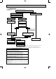
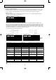
OC294-D-1.qxp 05.3.9 11:01 AM Page 24 Applicable extension pipe for each model The height difference between indoor and outdoor unit should be kept within 30 m for all models. (1) 1:1 system (a) Maximum pipe length
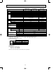
Pipe length for 1:1 system Liquid OD [6.35 pipe t0.8 (mm) Thickness Gas OD [12.7 [9.52 pipe t0.8 t0.8 (mm) Thickness 30m 10m RP1.6 RP2 RP2.5 RP3 RP4 RP5 RP6 [9.52 [12.7 t0.8 50m 50m 10m 10m [15.88 [12.7 t1.0 t0.8 30m 30m 10m 10m t0.8 [15.88 [19.05 [15.88 [19.05 t1.OC294-D-1.qxp 05.3.9 11:01 AM Page 25 (c) Capacity correction Cooling and heating capacity is lowered according to pipe length. Capacity can be obtained by referring to the capacity curves below. When the diameter of gas pipe is one size smaller than standard diameter, cooling capacity is lowered comparing to the standard diameter. The lowered capacity can be obtained by referring to capacity curves for gas pipe which is one size smaller than standard size.
OC294-D-1.qxp 05.3.9 11:01 AM Page 26 3 Capacity curve for PUHZ-RP2.5, 3 models 100 Heating RP2.5, RP3 Capacity ratio [%] 95 90 Cooling RP2.5 85 80 Cooling RP3 5 10 15 20 25 30 35 40 45 50 55 Corrected pipe length 4 When gas pipe is one size larger than standard size for PUHZ-RP4, 5 and 6. 1 Capacity can be obtained by referring to capacity curves of standard size.
OC294-D-1.qxp 05.3.9 11:01 AM Page 27 1. Refrigerant collecting (pump down) Perform the following procedures to collect the refrigerant when moving the indoor unit or the outdoor unit. 1Before collecting the refrigerant, first make sure that the all of the SW5 DIP switches for function changes on the control board of the outdoor unit are set to OFF. If all of the SW5 switches are not set to OFF, record the settings and then set all of the switches to OFF. Now, start refrigerant collecting operation.
OC294-D-1.qxp 11 05.3.9 11:01 AM Page 28 TROUBLESHOOTING 11-1. TROUBLESHOOTING Present and past error codes are logged and displayed on the wired remote controller and control board of outdoor unit. Actions to be taken for service, which depends on whether or not the inferior phenomenon is reoccurring at service, are summarized in the table below. Check the contents below before investigating details.
OC294-D-1.qxp 05.3.9 11:01 AM Page 29 11-2. CHECK POINT UNDER TEST RUN (MA remote controller) (1) Before test run • After installation of indoor and outdoor units, piping work and electric wiring work, re-check that there is no refrigerant leakage, loosened connections and incorrect polarity. • Measure impedance between the ground and the power supply terminal block(L, N) on the outdoor unit by 500V Merger and check that it is 1.0M" or over.
OC294-D-1.qxp 05.3.9 11:01 AM Page 30 wPress the remote controller’s CHECK button twice to perform self-diagnosis. See the table below for the contents of LCD display. LCD P1 P2 P4 P5 P6 P8 P9 Contents of inferior phenomena Abnormality of room temperature thermistor Abnormality of pipe temperature thermistor/Liquid Abnormality of drain sensor Drain overflow protection is working. Freezing/overheating protection is working. Abnormality of pipe temperature Abnormality of pipe temperature thermistor/Cond.
OC294-D-2.qxp 05.3.9 11:03 AM Page 31 11-3. MALFUNCTION-DIAGNOSIS METHOD BY REMOTE CONTROLLER 11-3-1. Error history of unit (1) Wired remote controller Mode number ON OFF ˚C CLOCK ˚C STAND BY DEFROST ERROR CODE NOT AVAILABLE TEMP. FILTER CHECK MODE TEST RUN FUNCTION ON/OFF FILTER CHECK TEST TIMER SET PAR-20MAA 1 “CHECK” and refrigerant address are displayed at set temperature display. Error code and unit number are displayed at clock display alternately.
OC294-D-2.qxp 05.3.9 11:03 AM (2) (3) 5 (1) b) (2) (3) Page 32 4 To cancel self-diagnosis There are following two methods to cancel self-diagnosis: Press the H “CHECK” button twice within three seconds. ➜Self-diagnosis is cancelled and the display screen will return to the status before self-diagnosis. Press the I “ON/OFF” button. ➜Self-diagnosis is cancelled and indoor unit will stop. This operation is ineffectual when the operation of remote controller is prohibited.
OC294-D-2.qxp 05.3.9 11:03 AM Page 33 (2) Digital wireless remote controller When a malfunction occurs to air conditioner, both indoor unit and outdoor unit will stop and operation lamp blinks to inform unusual stop. [Procedure] 1. Press the CHECK button twice. • "CHECK" lights, and refrigerant address "00" flashes. • Check that the remote controller's display has stopped before continuing. 2.
OC294-D-2.qxp 05.3.9 11:03 AM Page 34 11-3-2. Wired Remote controller Diagnosis If operation can not be carried out from remote controller, try remote controller diagnosis with following process. 1 a) 1 First, check the electricity current marker. When correct voltage (DC12V) is not supplied to remote controller, the electricity current marker is put out. If the electricity current marker is not lighted, check the remote controller wiring and the indoor units.
OC294-D-2.qxp 05.3.9 11:03 AM Page 35 11-4. SELF-DIAGNOSIS ACTION TABLE (Note 1) Refer to indoor unit section for code P and code E. Error Code Meaning of error code and detection method None — Case Judgment and action 1 No voltage is supplied to terminal 1 Check following items. block(TB1) of outdoor unit. a) Power supply breaker a) Power supply breaker is put b) Connection of power supply terminal block. off.
OC294-D-2.qxp 05.3.9 11:03 AM Page 36 Error Code Meaning of error code and detection method Indoor/outdoor unit connector mis-wiring, excessive number of units (4 units or more) 1. Outdoor controller circuit board can automatically check the number of connected indoor units. Abnormal if the number cannot be checked automatically due to mis-wiring of indoor/outdoor unit connecting wire and etc. after power is turned on for 4 minutes. EA 2.
OC294-D-2.qxp 05.3.9 11:03 AM Page 37 Error Code Meaning of error code and detection method Abnormal high pressure (High-pressure switch 63H worked) Abnormal if high-pressure switch 63H worked ( w ) during compressor operation. w RP1.6-2VHA : 4.15 MPa RP2.5-6VHA : 4.41 MPa RP2.5-6VHA1 : 4.15 MPa RP4-6YHA : 4.
OC294-D-2.qxp 05.3.9 11:03 AM Page 38 Judgment and action Case Error Code Meaning of error code and detection method Open/short circuit of discharge 1 Disconnection or contact temperature thermistor (TH4) failure of connector (TH4) on the outdoor controller circuit Abnormal if open (3: or less) or short board. (217: or more) is detected during U3 compressor operation.
OC294-D-2.qxp 05.3.9 11:03 AM Page 39 Case Error Code Meaning of error code and detection method Abnormality of power module 1 Outdoor stop valve is closed. Check abnormality by driving power module 2 Decrease of power supply voltage in case overcurrent is detected.
OC294-D-2.qxp 05.3.9 11:03 AM Page 40 Error Code Meaning of error code and detection method UF (4100) Compressor overcurrent interruption (When compressor locked) Abnormal if overcurrent of DC bus or compressor is detected within 30 seconds after compressor starts operating. Case Judgment and action 1 Open stop valve. 2 Check facility of power supply. 1 Stop valve is closed. 2 Decrease of power supply voltage 3 Correct the wiring (U•V•W phase) to 3 Looseness, disconnection or compressor.
OC294-D-2.qxp 05.3.9 11:03 AM Page 41 Case Error Code Meaning of error code and detection method Remote controller communication error 1 Defective communication cir(Signal receiving error) cuit of remote controller (1) Abnormal if any signal from IC of refrig- 2 Defective communication cirerant address “0” could not be normally cuit of indoor controller board received for three minutes.
OC294-D-2.qxp 05.3.9 11:03 AM Page 42 Error Code Meaning of error code and detection method P8 Abnormality of pipe temperature 1 Slight temperature difference between indoor room Detected as abnormal when the pipe temtemperature and pipe utes later of compressor start and 6 mintemperature thermistor utes later of the liquid or condenser/evapo• Shortage of refrigerant rator pipe is out of cooling range.
OC294-D-2.qxp 05.3.9 11:03 AM Page 43 Error Code Meaning of error code and detection method A6 (6606) Case Judgment and action Communication error with communication processor Defective communication between unit processor and transmission processor Note) The address and attribute display at remote controller indicate the controller that detected abnormality. 1 Data of transmission processor or unit processor is not transmitted normally because of accidental trouble such as noise or thunder surge.
OC294-D-2.qxp 05.3.9 11:03 AM Page 44 From the previous page. Error Code Meaning of error code and detection method Case Judgment and action 4. If displayed address or attribute is remote controller, Indoor unit detects abnormality when indoor unit transmitted to remote controller and there was no reply (ACK).
OC294-D-2.qxp 05.3.9 11:03 AM Page 45 Error Code Meaning of error code and detection method M-NET•NO RESPONSE Abnormal if a massage was transmitted and there were reply (ACK) that massage was received, but response command does not return. Transmitting side detects abnormality every 30 seconds, six times continuously. Note) The address and attribute displayed at remote controller is indicate the controller that did not reply (ACK).
OC294-D-2.qxp 05.3.9 11:03 AM Page 46 Phenomena 4. Even controlling by the wireless remote controller no beep is heard and the unit does not start operating. Operation display is indicated on wireless remote controller. Factor Countermeasure 1The pair number settings of the wireless remote controller and indoor controller board are mismatched. 1Check the pair number settings. 5. When operating by the wireless remote controller, beep sound is heard, however, unit does not start operating.
OC294-D-2.qxp 05.3.9 11:03 AM Page 47 11-6. HOW TO CHECK THE PARTS PUHZ-RP1.6HA PUHZ-RP2.5VHA1 PUHZ-RP4VHA PUHZ-RP5VHA1 PUHZ-RP4YHA PUHZ-RP2VHA PUHZ-RP3VHA PUHZ-RP4VHA1 PUHZ-RP6VHA PUHZ-RP5YHA PUHZ-RP2.5VHA PUHZ-RP3VHA1 PUHZ-RP5VHA PUHZ-RP6VHA1 PUHZ-RP6YHA Check points Parts name Thermistor (TH3) Disconnect the connector then measure the resistance using a tester.
OC294-D-2.qxp 05.3.9 11:03 AM Page 48 Check method of DC fan motor (fan motor / outdoor controller circuit board) 1 Notes · High voltage is applied to the connecter (CNF1, 2) for the fan motor. Give attention to the service. · Do not pull out the connector (CNF1, 2) for the motor with the power supply on. (It causes trouble of the outdoor controller circuit board and fan motor.) 2 Self check Symptom : The outdoor fan cannot turn around.
OC294-D-2.qxp 05.3.9 11:03 AM Page 49 11-7. HOW TO CHECK THE COMPONENTS 50 Low temperature thermistors • Thermistor (TH3) • Thermistor (TH6) • Thermistor (TH7) Resistance (k") 40 Thermistor R0 = 15k' ± 3% B constant = 3480 ± 2% 1 1 Rt =15exp{3480( 273+t – 273 )} 0: 15k' 30: 4.3k' 10: 9.6k' 40: 3.0k' 20: 6.3k' 25: 5.
OC294-D-2.qxp 05.3.9 11:03 AM Page 50 Linear expansion valve (1) Operation summary of the linear expansion valve. • Linear expansion valve open/close through stepping motor after receiving the pulse signal from the outdoor controller board. • Valve position can be changed in proportion to the number of pulse signal.
OC294-D-2.qxp 05.3.9 11:03 AM Page 51 (3) How to attach and detach the coil of linear expansion valve (Except RP4-RP6YHA) Linear expansion valve is separable into the main body and the coil as shown in the diagram below. Main body Coil Lead wire Stopper Hold the lower part of the main body (shown as A) firmly so that the main body does not move and detach the coil by pulling it upward. Be sure to detach the coil holding main body firmly.
OC294-D-2.qxp 05.3.9 11:03 AM Page 52 11-8. EMERGENCY OPERATION (1) When the error codes shown below are displayed on outdoor unit or microcomputer for wired remote controller or indoor unit has a failure, but no other problems are found, emergency operation will be available by setting the emergency operation switch (SWE) to ON and short-circuiting the connector (CN31) on outdoor controller board. ●When following abnormalities occur, emergency operation will be available.
OC294-D-2.qxp 05.3.9 11:03 AM Page 53 11-9. TEST POINT DIAGRAM Outdoor controller circuit board PUHZ-RP1.6VHA PUHZ-RP4VHA PUHZ-RP2VHA PUHZ-RP4VHA1 PUHZ-RP2.5VHA PUHZ-RP5VHA PUHZ-RP2.5VHA1 PUHZ-RP5VHA1 PUHZ-RP3VHA PUHZ-RP6VHA PUHZ-RP3VHA1 PUHZ-RP6VHA1 FAN11•FAN21 (FAN21 is only for RP4-6VHA.) Connect to fan motor (MF). FAN12•FAN22 (FAN22 is only for RP4-6VHA.) Connect to fan motor (MF) (Detection of position) 1 to 5 5V DC pulse 2 to 5 (Detected while the 3 to 5 motor is rotating.
OC294-D-2.qxp 05.3.9 11:03 AM Page 54 Outdoor controller circuit board PUHZ-RP4YHA PUHZ-RP5YHA PUHZ-RP6YHA CNS Communication power supply ZD71 Voltage developed across: 16-30V DC (Branch box/outdoor unit connecting wire) TEST POINT1 is high voltage.
OC294-D-2.qxp 05.3.9 11:03 AM Page 55 Outdoor noise filter circuit board PUHZ-RP1.6VHA PUHZ-RP2VHA LI, NI Voltage of 220-240V AC is input. (Connect to the terminal block(TB1)) EI Connect to the earth CNAC1, CNAC2 220-240V AC (Connect to the outdoor controller circuit board (CNAC)) CN5 Primary current (Connect to the outdoor power circuit board (CN5)) LO, NO Voltage of 220-240V AC is output.
OC294-D-2.qxp 05.3.9 11:03 AM Page 56 Outdoor noise filter circuit board PUHZ-RP2.5VHA PUHZ-RP2.5VHA1 PUHZ-RP3VHA PUHZ-RP3VHA1 EI Connect to the earth CNAC1, CNAC2 220-240V AC (Connect to the outdoor controller circuit board (CNAC)) CN5 Primary current (Connect to the outdoor power circuit board (CN5)) CN52C 52C relay signal (Connect to the outdoor controller circuit board (CN52C)) LO, NO Voltage of 220-240V AC is output. (Connect ACL) 56 LI, NI Voltage of 220-240V AC is input.
OC294-D-2.qxp 05.3.
OC294-D-2.qxp 05.3.
OC294-D-2.qxp 05.3.9 11:03 AM Page 59 Brief Check of DIP-IPM and DIP-PFC W Usually, they are in a state of being short-circuited if they are broken. Measure the resistance in the following points (connectors, etc.). If they are short-circuited, it means that they are broken. 1. Check of DIP-IPM P2 - U , P2 - V , P2 - W , N2 - U , N2 - V , N2 - W 2. Check of DIP-PFC P1 - L , P1 - N , L - N1 , N - N1 Outdoor power circuit board PUHZ-RP1.6VHA PUHZ-RP2VHA PUHZ-RP2.5VHA PUHZ-RP2.
OC294-D-2.qxp 05.3.9 11:03 AM Page 60 Brief Check of POWER MODULE W Usually, they are in a state of being short-circuited if they are broken. Measure the resistance in the following points (connectors, etc.). If they are short-circuited, it means that they are broken. 1. Check of POWER MODULE 1.Check of DIODE circuit L - P1 , N - P1 , L - N1 , N - N1 2.
OC294-D-3.qxp 05.3.9 11:04 AM Page 61 Brief Check of POWER MODULE W Usually, they are in a state of being short-circuited if they are broken. Measure the resistance in the following points (connectors, etc.). If they are short-circuited, it means that they are broken. 1. Check of POWER MODULE 1.Check of DIODE circuit L1 - P1 , L2 - P1 , L3 - P1 , L1 - N1 , L2 - N1 , L3 - N1 2.
OC294-D-3.qxp 05.3.
OC294-D-3.qxp 05.3.9 11:04 AM Page 63 11-10. FUNCTION OF SWITCHES, CONNECTORS AND JUMPERS (1) Function of switches Type of Switch No. switch SW1 ON OFF Compulsory defrosting Start Normal When compressor is working in heating operation.
OC294-D-3.qxp 05.3.9 11:04 AM Type of Switch No. Switch 1 SW5 Page 64 Action by the switch operation ON OFF — — Function No function Power failure automatic recovery w1 Auto recovery No auto recovery When power supply ON 3 No function — — — 4 No function — — — 1 RP1.6-6VHA only Switch to “Low-level SW7 — 2 2 1 Dip switch Effective timing 2 Sound Priority Mode” w2 OFF ON OFF Low-level Sound Priority Mode Cooling Heating Mode 1 Regulate max Hz Regulate max Hz to spec.
OC294-D-3.qxp 05.3.9 11:04 AM Page 65 (2) Function of connectors and jumpers Types Connector Function Connector CN31 Emergency operation SW6 or Jumper (RP1.6-6VHA) SW6-1 (J1) SW6-2 (J2) SW6-3 (J3) SW6-4 (J4) SW6-5 (J5) SW6-6 (J6) Action by open/ short operation Short Open Start Normal :ON(Short) Model SW6(JP) 1 When power supply ON :OFF(Open) 3 4 5 6 PUHZ-RP1.6VHA PUHZ-RP2VHA PUHZ-RP2.
OC294-D-3.qxp 05.3.9 11:04 AM Page 66 The blinking patterns of both LED1(green) and LED2(red) indicate the types of abnormality when it occurs. Types of abnormality can be indicated in details by connecting an optional part ‘A-Control Service Tool (PAC-SK52ST)’ to connector CNM on outdoor controller board.
OC294-D-3.qxp 05.3.9 11:04 AM Indication Outdoor controller board LED1 (Green) LED2 (Red) Page 67 Error Contents Error code w1 3 blinking 1 blinking Abnormality of shell thermostat U2 and discharging temperature (TH4) Abnormality of super heat due U7 to low discharge temperature 2 blinking Abnormal high pressure (High U1 pressure switch 63H worked.) Detailed reference page Inspection method 1Check if stop valves are open.
OC294-D-3.qxp 05.3.9 11:04 AM Page 68 [When option part ‘A-Control Service Tool(PAC-SK52ST)’ is connected to outdoor controller board(CNM)] Digital indicator LED1 displays 2 digit number or code to inform operation condition and the meaning of error code by controlling DIP SW2 on ‘A-Control Service Tool’.
OC294-D-3.qxp 05.3.9 11:04 AM SW2 setting ON Page 69 Pipe temperature / Liquid(TH3) – 40~90 1 2 3 4 5 6 Discharge temperature (TH4) 3~217 ON 1 2 3 4 5 6 ON Explanation for display Unit – 40~90 (When the coil thermistor detects 0: or below, “–” and temperature are displayed by turns.) (Example) When -10:; 0.5 secs. 0.5secs. 2 secs. 10 : 3~217 (When the discharge thermistor detects 100: or more, hundreds digit, tens digit and ones digit are displayed by turns.) (Example) When 105:; 0.5 secs. 0.
OC294-D-3.qxp 05.3.9 11:04 AM SW2 setting ON Page 70 Display detail Explanation for display Unit Pipe temperature / Liquid(TH3) on error occurring – 40~90 – 40~90 (When the coil thermistor detects 0: or below, “–” and temperature are displayed by turns.) (Example) When –15:; 0.5 secs. 0.5secs. 2 secs.
OC294-D-3.qxp 05.3.9 11:04 AM SW2 setting Page 71 Explanation for display Display detail The number of connected indoor units ON 0~3 (The number of connected indoor units are displayed.) Unit Unit 1 2 3 4 5 6 Capacity setting display Displayed as an outdoor capacity code. Capacity RP1.6V RP2V RP2.
OC294-D-3.qxp 05.3.9 11:04 AM SW2 setting ON Page 72 Explanation for display Display detail Indoor setting temperature 17~30 17~30 Outdoor pipe temperature / Cond./ Eva. (TH6) -39~88 -39~88 (When the temperature is 0: or less, “–” and temperature are displayed by turns.) Outdoor outside temperature (TH7) -39~88 -39~88 (When the temperature is 0: or less, “–” and temperature are displayed by turns.
OC294-D-3.qxp 05.3.9 11:04 AM SW2 setting ON Page 73 Explanation for display Display detail 0~100 (When the capacity is 100% hundreds digit, tens digit and ones digit are displayed by turns.) (Example) When 100%; 0.5 secs. 0.5secs. 2 secs. 1 00 Capacity save 0~255 When air conditioner is connected to M-NET and capacity save mode is demanded, “0”~”100” is displayed. 1 2 3 4 5 6 Unit % When there is no setting of capacity save “100” is displayed.
OC294-D-3.qxp 05.3.9 11:04 AM SW2 setting Page 74 Display detail Explanation for display LEV-A opening pulse on error occurring 0~480 0~480 (When it is 100 pulse or more, hundreds digit, tens digit and ones digit are displayed by turns.) (Example) When 130 pulse; 0.5 secs. 0.5secs. 2 secs.
OC294-D-3.qxp 05.3.9 11:04 AM SW2 setting Page 75 Display detail Explanation for display Unit Discharge super heat on error occurring SHd 0~255 0~255 (When the temperature is 100°C or more, hundreds digit, tens digit and ones digit are displayed by turns.) (Example) When 150°C; 0.5 secs. 0.5secs. 2 secs. 1 50 : 0~130 (When the temperature is 100°C or more, hundreds digit, tens digit and ones digit are displayed by turns.) (Example) When 115°C; 0.5 secs. 0.5secs. 2 secs.
OC294-D-3.qxp 05.3.9 11:04 AM Page 76 11-11. SELECTING FUNCTIONS USING THE REMOTE CONTROLLER Each function can be set according to necessity using the remote controller. The setting of function for each unit can only be done by the remote controller. Select function available from the table 1.
Function selections (1) Functions available when setting the unit number to 00 (Select 00 referring to 4 setting the indoor unit number on Page 73.OC294-D-3.qxp 05.3.9 11:04 AM Page 77 11-11-1. Selecting functions using the wired remote controller [Flow of function selection procedure] The flow of function selection procedure is shown below. The flow is described in case of setting indoor temperature detecting shown in table 1 on the preceding page. Refer to procedure 1 to 0 when actually setting functions. Selecting functions using the wired remote controller 1 Check the function selection setting. 2 Switch to function setting mode.
OC294-D-3.qxp 05.3.9 11:04 AM Page 78 4 Setting the indoor unit number Press D(CLOCK ON OFF) and [--] will start to flash in the unit number display (4) . Press C (TIMER SET) button to select the unit number from 00, 01, 02, 03, 04, and AL. 4 FUNCTION FUNCTION •Set the unit number to 00 if the mode such as power failure automatic recovery, indoor temperature detecting or LOSSNAY connectivity is desired to be selected.
OC294-D-3.qxp 05.3.9 11:04 AM Page 79 8 Registering the settings from steps 3 to 7 into memory The mode and setting numbers (1)(2) will start to flash when the MODE button E is pressed and registration will begin. The numbers are set when the flashing stays lit. FUNCTION FUNCTION 1 2 1 2 WIf [---] appears in the room temperature display as the mode/setting number, or if a flashing [88] display appears, a transmission problem may have occurred.
OC294-D-3.qxp 05.3.9 11:04 AM Page 80 11-11-2. Selecting functions using the wireless remote controller (Type C) Functions can be selected with the wireless remote controller. Function selection using wireless remote controller is available only for refrigerant system with wireless function. Refrigerant address cannot be specified by the wireless remote controller. [Flow of function selection procedure] The flow of the function selection procedure is shown below.
OC294-D-3.qxp 05.3.9 11:04 AM 12 Page 81 DISASSEMBLY PROCEDURE PUHZ-RP1.6VHA PUHZ-RP2VHA PHOTOS OPERATING PROCEDURE 1. Removing the top panel, service panel, front panel and Photo 1 back panel (1) Remove the top panel fixing screws (4 ✕ 10), one from the right and two from the eft side, and detach the top panel. Top panel Top panel fixing screws Back panel (2) Remove 1 service panel fixing screw (4 ✕ 10) and detach the service panel by pulling it downward. (See photo 2.
OC294-D-3.qxp 05.3.9 11:04 AM Page 82 OPERATING PROCEDURE PHOTOS 3. Removing the electrical parts box Photo 5 (1) Remove the service panel. (See photo 2.) (2) Remove the top panel. (See photo 1.) (3) Remove the front panel. (See photo 1.) (4) Disconnect the indoor/outdoor connecting wire from terminal block.
OC294-D-3.qxp 05.3.9 11:04 AM Page 83 OPERATING PROCEDURE PHOTOS 5. Removing the thermistor (TH7) Photo 7 (1) Remove the service panel. (See figure 1.) (2) Remove the top panel. (See figure 1.) (3) Disconnect the connector TH7 (red) on the controller circuit board in the electrical parts box. (4) Loosen the clamp for the lead wire in the rear of the electrical parts box. (See photo 4.) (5) Pull out the thermistor (TH7) from the sensor holder.
OC294-D-3.qxp 05.3.9 11:04 AM Page 84 OPERATING PROCEDURE PHOTOS 8. Removing the four-way valve Photo 10 (1) Remove the service panel. (See photo 2.) (2) Remove the top panel. (See photo 1.) (3) Remove the front panel. (See photo 1.) (4) Remove the back panel. (See photo 1.) (5) Remove the electrical parts box. (See photo 5.) Linear expansion valve coil (LEV A) (6) Remove the solenoid valve coil (See photo 8.) Linear expansion (7) Collect the refrigerant.
OC294-D-3.qxp 05.3.9 11:04 AM Page 85 OPERATING PROCEDURE PHOTOS 12. Removing the motor for compressor (MC) (1) Remove the service panel. (See photo 2.) (2) Remove the top panel. (See photo 1.) (3) Remove the front panel. (See photo 1.) (4) Remove the back panel. (See photo 1.) (5) Remove the electrical parts box. (See photo 5.) (6) Remove 3 separator fixing screws (4 ✕ 10) and remove the separator. (7) Collect the refrigerant. (8) Remove 3 compressor fixing nuts by using a spanner or a monkey wrench.
OC294-D-3.qxp 05.3.9 11:04 AM Page 86 PUHZ-RP2.5VHA PUHZ-RP2.5VHA1 PUHZ-RP3VHA PUHZ-RP3VHA1 PHOTOS & ILLUSTRATION OPERATING PROCEDURE 1. Removing the service panel and top panel (1) Remove 3 service panel fixing screws (5 ✕ 10) and slide the hook on the right downward to remove the service panel. (2) Remove screws (3 for front, 3 for rear/5 ✕ 10) of the top panel and remove it.
OC294-D-3.qxp 05.3.9 11:04 AM Page 87 OPERATING PROCEDURE PHOTOS 4. Removing the thermistor (TH6) (1) Remove the service panel. (See figure 1.) (2) Remove the top panel. (See figure 1.) (3) Disconnect the connectors, TH6 and TH7 (red), on the controller circuit board in the electrical parts box. Photo 4 Electrical parts box Controller circuit board (C.B.) Thermistor (TH6) (4) Loosen the clamp for the lead wire in the rear of the electrical parts box.
OC294-D-3.qxp 05.3.9 11:04 AM Page 88 PHOTOS OPERATING PROCEDURE 7. Removing the solenoid valve coil (21S4), linear expansion valve coil (LEV(A), LEV(B)) and solenoid valve coil (SV) (1) Remove the service panel. (See figure 1.) (2) Remove the top panel. (See figure 1.) (3) Remove the electrical parts box. (See photo 3.) [Removing the solenoid valve coil ] (4) Remove solenoid valve coil fixing screw (M4 ✕ 6).
OC294-D-3.qxp 05.3.9 11:04 AM Page 89 OPERATING PROCEDURE PHOTOS 10. Removing the bypass valve (1) Remove the service panel. (See figure 1.) (2) Remove the top panel. (See figure 1.) (3) Remove the electrical parts box. (See photo 3.) (4) Remove 3 right side panel fixing screws (5 ✕ 10) in the rear of the unit and remove the right side panel. (5) Remove the bypass valve solenoid coil. (See photo 7.). (6) Collect the refrigerant. (7) Remove the welded part of bypass valve.
OC294-D-3.qxp 05.3.9 11:04 AM Page 90 OPERATING PROCEDURE PHOTOS 13. Removing the motor for compressor (MC) (1) Remove the service panel. (See figure 1.) (2) Remove the top panel. (See figure 1.) (3) Remove 2 front cover panel fixing screws (5 ✕ 10) and remove the front cover panel. (See photo 3.) (4) Remove 2 back cover panel fixing screws (5 ✕ 10) and remove the back cover panel. (5) Remove the electrical parts box. (See photo 3.
OC294-D-4.qxp 05.3.9 11:06 AM Page 91 PUHZ-RP4VHA PUHZ-RP5VHA PUHZ-RP6VHA PHOTOS & ILLUSTRATION OPERATING PROCEDURE 1. Removing the service panel and top panel (1) Remove 3 service panel fixing screws (5 ✕ 10) and slide the hook on the right downward to remove the service panel. (2) Remove screws (3 for front, 3 for rear/5 ✕ 10) of the top panel and remove it. Figure 1 Top panel fixing screws Top panel Service panel Grille fixing screws Slide Fan grille Grille fixing screws 2.
OC294-D-4.qxp 05.3.9 11:06 AM Page 92 OPERATING PROCEDURE PHOTOS 4. Removing the thermistor (TH6) (1) Remove the service panel. (See figure 1.) (2) Remove the top panel. (See figure 1.) (3) Disconnect the connectors, TH6 and TH7 (red), on the controller circuit board in the electrical parts box. (4) Loosen the clamp for the lead wire in the rear of the electrical parts box. (5) Pull out the thermistor (TH6) from the sensor holder.
OC294-D-4.qxp 05.3.9 11:06 AM Page 93 PHOTOS OPERATING PROCEDURE 7. Removing the solenoid valve coil (21S4), and linear expansion valve coil (LEV(A), LEV(B)) (1) Remove the service panel. (See figure 1.) (2) Remove the top panel. (See figure 1.) Photo 7 Linear expansion valve coil (LEV A) Solenoid valve coil fixing screw [Removing the solenoid valve coil ] (3) Remove four-way valve solenoid coil fixing screw (M4 ✕ 6).
OC294-D-4.qxp 05.3.9 11:06 AM Page 94 OPERATING PROCEDURE PHOTOS 10. Removing solenoid valve coil (SV) and bypass valve (1) Remove the service panel. (See figure 1.) (2) Remove the top panel. (See figure 1.) (3) Remove 3 right side panel fixing screws (5 ✕ 10) in the rear of the unit and remove the right side panel. (4) Remove the bypass valve solenoid coil fixing screw (M4 ✕ 6). (5) Remove the solenoid valve coil by sliding the coil upward.
OC294-D-4.qxp 05.3.9 11:06 AM Page 95 OPERATING PROCEDURE PHOTOS 13. Removing the motor for compressor (MC) (1) Remove the service panel. (See figure 1.) (2) Remove the top panel. (See figure 1.) (3) Remove 2 front cover panel fixing screws (5 ✕ 10) and remove the front cover panel. (See photo 3.) (4) Remove 2 back cover panel fixing screws (5 ✕ 10) and remove the back cover panel. (5) Remove the electrical parts box. (See photo 3.
OC294-D-4.qxp 05.3.9 11:06 AM Page 96 PUHZ-RP4VHA1 PUHZ-RP5VHA1 PUHZ-RP6VHA1 PHOTOS & ILLUSTRATION OPERATING PROCEDURE 1. Removing the service panel and top panel (1) Remove 3 service panel fixing screws (5 ✕ 10) and slide the hook on the right downward to remove the service panel. (2) Remove screws (3 for front, 3 for rear/5 ✕ 10) of the top panel and remove it. Figure 1 Top panel fixing screws Top panel Service panel Slide Grille fixing screws Fan grille Grille fixing screws 2.
OC294-D-4.qxp 05.3.9 11:06 AM Page 97 OPERATING PROCEDURE PHOTOS 4. Removing the thermistor (TH6) (1) Remove the service panel. (See figure 1.) (2) Remove the top panel. (See figure 1.) (3) Disconnect the connectors, TH6 and TH7 (red), on the controller circuit board in the electrical parts box. (4) Loosen the clamp for the lead wire in the rear of the electrical parts box. (5) Pull out the thermistor (TH6) from the sensor holder.
OC294-D-4.qxp 05.3.9 11:06 AM Page 98 PHOTOS OPERATING PROCEDURE Photo 7 7. Removing the solenoid valve coil (21S4), and linear expansion valve coil (LEV(A), LEV(B)) (1) Remove the service panel. (See figure 1.) (2) Remove the top panel. (See figure 1.) Solenoid valve coil (21S4) [Removing the solenoid valve coil ] (3) Remove four-way valve solenoid coil fixing screw (M4 ✕ 6).
OC294-D-4.qxp 05.3.9 11:06 AM Page 99 OPERATING PROCEDURE PHOTOS 10. Removing solenoid valve coil (SV) and bypass valve (1) Remove the service panel. (See figure 1.) (2) Remove the top panel. (See figure 1.) (3) Remove 3 right side panel fixing screws (5 ✕ 10) in the rear of the unit and remove the right side panel. (4) Remove the bypass valve solenoid coil fixing screw (M4 ✕ 6). (5) Remove the solenoid valve coil by sliding the coil upward.
OC294-D-4.qxp 05.3.9 11:06 AM Page 100 OPERATING PROCEDURE PHOTOS 13. Removing the motor for compressor (MC) (1) Remove the service panel. (See figure 1.) (2) Remove the top panel. (See figure 1.) (3) Remove 2 front cover panel fixing screws (5 ✕ 10) and remove the front cover panel. (See photo 3.) (4) Remove 2 back cover panel fixing screws (5 ✕ 10) and remove the back cover panel. (5) Remove the electrical parts box. (See photo 3.
OC294-D-4.qxp 05.3.9 11:06 AM Page 101 PUHZ-RP4YHA PUHZ-RP5YHA PUHZ-RP6YHA PHOTOS & ILLUSTRATION OPERATING PROCEDURE 1. Removing the service panel and top panel (1) Remove 3 service panel fixing screws (5 ✕ 10) and slide the hook on the right downward to remove the service panel. (2) Remove screws (3 for front, 3 for rear/5 ✕ 10) of the top panel and remove it. Figure 1 Top panel fixing screws Top panel Service panel Slide Grille fixing screws Fan grille Grille fixing screws 2.
OC294-D-4.qxp 05.3.9 11:06 AM Page 102 From the previous page. PHOTOS & ILLUSTRATION OPERATING PROCEDURE (5) Remove the terminal cover and disconnect the compressor lead wire. (6) Remove 2 electrical parts box fixing screws (4 ✕ 10) and detach the electrical parts box by pulling it upward. The electrical parts box is fixed with 2 hooks on the left and 1 hook on the right. Photo 4 Electrical parts box Electrical parts box fixing screw 4.
OC294-D-4.qxp 05.3.9 11:06 AM Page 103 PHOTOS OPERATING PROCEDURE 5. Removing the thermistor (TH6) (1) Remove the service panel. (See figure 1.) (2) Remove the top panel. (See figure 1.) (3) Disconnect the connectors, TH6 and TH7 (red), on the controller circuit board in the electrical parts box. (4) Loosen the 2 wire clamps on top of the electrical parts box. (5) Pull out the thermistor (TH6) from the sensor holder.
OC294-D-4.qxp 05.3.9 11:06 AM Page 104 PHOTOS OPERATING PROCEDURE 8. Removing the solenoid valve coil (21S4), Photo 13 and linear expansion valve coil (LEV(A), LEV(B)) (1) Remove the service panel. (See figure 1.) Solenoid valve coil (2) Remove the top panel. (See figure 1.) (21S4) [Removing the solenoid valve coil ] (3) Remove four-way valve solenoid coil fixing screw (M4 ✕ 6).
OC294-D-4.qxp 05.3.9 11:06 AM Page 105 OPERATING PROCEDURE PHOTOS 11. Removing solenoid valve coil (SV) and bypass valve (1) Remove the service panel. (See figure 1.) (2) Remove the top panel. (See figure 1.) (3) Remove 3 right side panel fixing screws (5 ✕ 10) in the rear of the unit and remove the right side panel. (4) Remove the bypass valve solenoid coil fixing screw (M4 ✕ 6). (5) Remove the solenoid valve coil by sliding the coil upward.
OC294-D-4.qxp 05.3.9 11:06 AM Page 106 OPERATING PROCEDURE PHOTOS 13. Removing the reactors (ACL1, ACL2, ACL3) Photo 17 (1) Remove the service panel. (See figure 1.) (2) Remove the top panel. (See figure 1.) (3) Remove the 6 screws, screw 8 and 9 (5 ✕ 10), that fix the front panel and remove the front panel. (See photo 3.
OC294-D-4.qxp 05.3.9 11:06 AM Page 107 OPERATING PROCEDURE PHOTOS 14. Removing the motor for compressor (MC) Photo 20 (1) Remove the service panel. (See figure 1.) (2) Remove the top panel. (See figure 1.) (3) Remove 2 front cover panel fixing screws (5 ✕ 10) and remove the front cover panel. (See photo 3.) (4) Remove 2 back cover panel fixing screws (5 ✕ 10) and Valve bed remove the back cover panel. (5) Remove the electrical parts box. (See photo 3.
OC294-D-4.qxp 13 05.3.9 11:06 AM Page 108 PARTS LIST STRUCTURAL PARTS PUHZ-RP1.6VHA PUHZ-RP2VHA 10 9 8 7 6 13 12 1 11 2 3 4 , Q ty/set No. Part No. Part Name Specification PUHZ-RP1.
OC294-D-4.qxp 05.3.9 11:06 AM Page 109 STRUCTURAL PARTS PUHZ-RP2.5VHA PUHZ-RP2.5VHA1 1 PUHZ-RP3VHA PUHZ-RP3VHA1 17 18 16 2 15 14 13 12 9 5 6 7 8 9 11 10 3 No. 1 4 Part No. — Part Name F.ST SCREW Specification (5✕10) , Q ty/set PUHZ-RP 2.
OC294-D-4.qxp 05.3.9 11:06 AM Page 110 STRUCTURAL PARTS PUHZ-RP4VHA PUHZ-RP4VHA1 PUHZ-RP5VHA PUHZ-RP5VHA1 PUHZ-RP6VHA PUHZ-RP6VHA1 17 2 1 18 16 15 14 13 12 9 3 5 6 7 8 9 11 10 4 No. Part No. 1 — Part Name Specificatio , Q ty/set PUHZ-RP 6 4 5 VHA, VHA1 (5✕10) 38 38 38 2 R01 E02 662 SIDE PANEL (L) 1 1 1 3 T7W E02 691 FAN GRILLE 2 2 2 4 T7W E02 667 FRONT PANEL 1 1 1 5 1 1 1 — F.ST SCREW SEPARATOR Remarks (Drawing No.
OC294-D-4.qxp 05.3.9 11:06 AM Page 111 STRUCTURAL PARTS PUHZ-RP4YHA 2 1 PUHZ-RP5YHA PUHZ-RP6YHA 17 18 16 15 14 13 12 9 3 5 6 7 8 9 10 11 4 Specificatio , Q ty/set PUHZ-RP 6 4 5 YHA (5✕10) 38 38 38 2 R01 E02 662 SIDE PANEL (L) 1 1 1 3 T7W E02 691 FAN GRILLE 2 2 2 4 T7W E02 667 FRONT PANEL 1 1 1 5 1 1 1 6 R01 E14 686 BASE ASSY 1 1 1 7 T7W E05 130 MOTOR SUPPORT 1 1 1 8 No. Part No. 1 — — — Part Name F.ST SCREW SEPARATOR Remarks (Drawing No.
OC294-D-4.qxp 05.3.9 11:06 AM Page 112 FUNCTIONAL PARTS PUHZ-RP1.
OC294-D-4.qxp 05.3.9 11:06 AM Page 113 Part numbers that is circled is not shown in the figure. , Q ty/set No. Part No. Part Name Specification Price Wining RecomRemarks Diagram mended PUHZ-RP1.6VHA (Drawing No.
OC294-D-4.qxp 05.3.9 11:06 AM Page 114 FUNCTIONAL PARTS PUHZ-RP2.5VHA PUHZ-RP2.
OC294-D-4.qxp No. 05.3.9 11:06 AM Page 115 Part No. Part Name Specification , Q ty/set PUHZ-RP Remarks 2.5 3 (Drawing No.) VHA VHA1 VHA VHA1 1 R01 E28 221 FAN MOTOR 1 1 1 1 2 R01 E01 115 PROPELLER 1 1 1 1 3 R01 E02 097 NUT 1 1 1 1 4 1 1 1 1 (BK00B055G19) 5 T7W E00 242 SOLENOID VALVE COIL 1 1 1 1 6 R01 E03 428 BYPASS VALVE 1 1 1 1 1 1 1 — ELECTRICAL PARTS BOX 7 R01 E15 425 CAPILLARY TUBE [4.0 ✕ [2.4 ✕ 500mm 1 8 R01 E16 425 CAPILLARY TUBE [2.
OC294-D-4.qxp 05.3.
OC294-D-4.qxp 05.3.9 11:06 AM Page 117 Part numbers that is circled is not shown in the figure. , Q ty/set No. Part No. Part Name Specification Price PUHZ-RP 4 5 6 Remarks (Drawing No.
OC294-D-4.qxp 05.3.
OC294-D-4.qxp 05.3.9 11:06 AM Page 119 Part numbers that are circled are not shown in the figures. , Q ty/set No. Part No. Part Name Specification Price PUHZ-RP 4 5 6 Remarks (Drawing No.
OC294-D-4.qxp 05.3.
OC294-D-4.qxp 05.3.9 11:06 AM Page 121 Part numbers that are circled are not shown in the figures. , Q ty/set No. Part No. Part Name Specification Price PUHZ-RP 4 5 6 Remarks (Drawing No.
OC294-D-4.qxp 14 05.3.9 11:06 AM Page 122 OPTIONAL PARTS 14-1. DRAIN SOCKET Part No. Applied models PAC-SG61DS-E PUHZ-RP1.6, 2, 2.5, 3, 4, 5, 6VHA PUHZ-RP4, 5, 6YHA 14-2. AIR OUTLET GUIDE Part No. Applied models PAC-SG59SG-E PUHZ-RP1.6, 2, 2.5, 3, 4, 5, 6VHA PUHZ-RP4, 5, 6YHA w PUHZ-RP4, 5, 6VHA needs two piece. 14-3. DRAIN PAN Part No. Applied models PAC-SG64DP-E PUHZ-RP1.6, 2, 2.5, 3, 4, 5, 6VHA PUHZ-RP4, 5, 6YHA 14-4. A CONTROL SERVICE TOOL Part No. Applied models PAC-SK52ST PUHZ-RP1.