
Engineering Manual
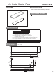

Air Outlet Shutter Plate PAC-SJ37SP-E
How to Use / How to Install
Air-outlet shutter plate Installation Manual
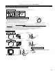
Checking for provided parts
1 Shutter plate
2
2 Shutter plate
1
Part #,
Name
Q'ty
Figure
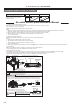
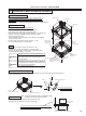
Fig.1
Fig.2
Main unit
Drain pipe
Refrigerant pipe
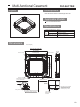
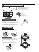
1) Turn OFF the main power (earth leakage breaker).
3) Slowly move the auto vane of which the shutter
plate is attached to its air outlet, and fully close.
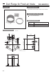
Air outlet
concave
portion
Grille
Shutter plate 1
(Peel off the release
liner and attach it.)
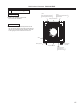
Shutter plate 2
Datum line for
Shutter plate 2
attachment
Datum line for
Shutter plate 2
attachment
Service panel for
on-site wiring
Align the service panel for on-site wiring as
shown below, and attach the shutter plate 2.
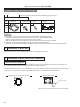
Vane motor
Vane motor
Auto vane (at fully closed position)
Connector
Lock release button
Grille
Shutter plate 1
(Installed to the main unit)
Auto vane
(at fully closed position)
2) Disconnect the vane motor connector from the grille of which the shutter plate 2 is attached
to its air outlet. (To disconnect, press the lock release button while pulling the connector
toward the arrow as shown below.) Insulate the disconnected connector with plastic tape.
Do not fully close the auto vane if no
shutter plate I attached to its air outlet.
Caution
●Otherwise, dew formation or dew drop,
or a unit malfunction may result.
Turn OFF the main power.
Warning
●The fan of the unit will run, which can cause accident or electric shock.
1. Locate the Shutter Plate installation position
●This is a part which is used to convert the number of air-outlet from "4 ways" to "3 ways" or "2 ways".
Note: Convert to "1 way" is not available.
●Select the outlet direction and decide the outlet to be closed.
Notes:
1. When the number of outlet is selected to "2 ways", be sure to explain to the customer that the filter should be cleaned once a month.
(Otherwise, the filter will be clogged, and the performance of the cooling and heating can be lower.)
2. When the number of outlet is selected to "3 ways" or "2 ways", the operation noise can be larger.
3. Never to select "2 ways" in the environment of high temperature and high humidity.
(It can cause dew drops.)
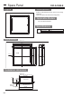
2. Installation of shutter plate (Fig.1)
●Install the shutter plate to the indoor unit so that it can fit the air-outlet concave portion.
Notes:
1. Install one piece of Shutter plate 1 per one air-outlet.
2. The installation should be done before the grille is installed.
3. The shutter plate must be installed not to cause wrinkle or gap.
(It can cause dew drops.)
4. When attaching the shutter plate to the blow outlet (marked ) between the refrigerant piping and the drain pump, attach the shutter plate 2.
3. Function setting
●When the number of air-outlet is changed, it is necessary to make function selection.
For the setting method, refer to the installation manual of the main unit.
4. Setting of the auto vane (Fig.2)
●It is possible to fix the auto vane of the grille to the fully closed position, which is applied to the air-outlet installed on the shutter plate.
Once the auto vane is fixed, the operation of a remote controller and all of automatic control will not be available.
Note that the fixed vane angle differs from the one which is displayed on the remote controller.
Make sure that the parts shown on the
right are in this bag, along with the
instruction sheet.
172