
Engineering Manual
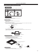
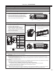

Raises drain generated during unit's operation to secure the
appropriate angle of the drain pipe.
Photo
Specications
PKA-A24KA7
PKA-A30KA7
PKA-A36KA7
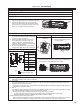
Drain Pump
PAC-SH94DM-E
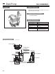
Unit : inch
Descriptions
Applicable Models
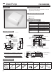
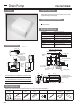
Dimensions
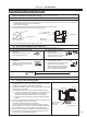
Required space for installation of Drain Pump
[Maintenance space]
Knock out hole
for piping
Flexible drain tube
(VP20) port (female)
Refrigerant pipe
(Two pipes can be
raised together)
Hole for
Indoor
unit
piping
31-1/2 (Max. lift)
19-11/16
(Max. lift)
3-7/64 7/8
10-27/32
11-13/16
6-9/16
11-13/16
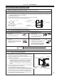
Dimension of Mounting plate
3-1/16
7-3/8
12-1/16
2-3/16 (Space for piping)
Mounting
plate
Indoor unit
Tube band position
Paper pattern
(M10 or W3/8)
6 - ø3/16 dia. hole
6 - ø1/2 dia. hole
(M4 x 35)
1-3/16
23/32
3-11/32
4-3/4
2-3/4
3-3/161-3/163-17/321-31/32
5/16
* The same space is
required for the left front
and rear piping.
* In case that there is a rim at the corner of ceiling,
consider the dimension of the rim before installation.
Obstruc-
tion
11-13/16
7/64
46-1/16
Drain Pump
9-7/8 or more
3-31/32 or more
14-3/8
4-5/16
or
more
21-21/32 or more
2-3/8 or less
*
3/16
Connected to drain outlet.
PVC pipe VP-20 (O.D. 26) can be
used
12 / 10.8W
220-240V 50Hz / 60Hz
Rated voltage
Power consumption
Operating current
Discharge lift
Discharge rate
0.114 / 0.092A
24
/h or more
Max. 500 mm from drain pump’s top
surface
External dimensions (inch)
11-13/16 (H) x 11-13/16 (W) x 7-3/8 (D)
Exterior
Cover : ABS resin (Munsell 6.4Y 8.9/0.4)
Drain piping
Driving motor
Single, shading type (Class E insulation)
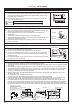
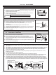
Accessories
* The items (B) – (F) are packed between main body and cover of the Drain Pump. Take them out after the cover removed.
(A) Drain
Pump
(B) Screw (C) Drain
tube
(D)
Drain tube
cover
(E) Tube clip (F) Pull tight (G) Paper
pattern
(H) Wiring
plate
x 1
(M4 x 16) x 1
(M4 x 35) x 6
x 1 x 1 x 1 x 1 x 1 x 1
(Make sure of the following items attached with the Drain Pump before installation.)
182