
Engineering Manual
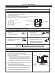

6. Test run
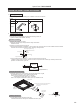
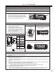
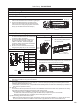
5-3 Electric wiring operation
(* Confirm that the power is off before starting the installation work.)
● Pull out the electric box as far as necessary
to connect the lead wires to the control board
connectors “CNP” and “CN4F”.
● Connect the lead wires with connectors to
the control board connectors “CNP” and
“CN4F”. At this time, remove the bypass
connector (will be unused) from the terminal
CN4F of the control board.
●
Be sure not to have the lead wires touch the
heat generator (heat sink) on the control board.
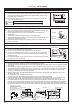
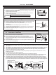
Electric circuit diagram
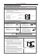
● After the installation of the Drain Pump has been completed, make sure that the drain works correctly and the
water does not leak from any part of connection.
(1) Pour water
Pour water approximately 800 cc to the drain pan. (* See the drain pipe [checking the drain flow] section in the
installation manual of the indoor unit.)
(* If the water is poured too much, it is possible that the drainage does not work due to alarm stop by activation of
drain over flow protection device.)
(2) Test run
In accordance with the procedure for test run in the installation manual for the indoor unit, operate the air cooling
and make sure that the drainage works and the water does not leak.
* When the Drain Pump is installed in winter season, the water must be drained.
To drain water, remove the drain plug under the Drain Pump. Prepare the pan to receive drain.
When the drainage has been completed, put the drain plug back in place.
(3) After checking, put the cover back in place.
* Make sure that the left end of the indoor unit perfectly comes on the point marked at 2-1. (If they
do not match,
the cover will not be able to be installed or there will be a gap between the cover and the indoor unit.)
Note: stands for terminal connection.
stands for connector joint.
Symbol Name
TB Terminal block
(indoor/outdoor
connecting line)
I.B Indoor control
board
CNP Connector
(Drain Pump)
CN4F Connector
(Float switch)
DP Drain Pump
FS Float switch
X1 Relay (Drain
Pump)
Electric box
Lead
wires
(* See the indoor unit installation section in the installation manual of the indoor unit.)
Indoor unit
Wiring plate
● Affix the wiring plate (H) to the
rear of the panel.
● After completing the electric wiring operation, make sure
that the hooks are securely caught on the unit, and then put
the electric box cover and panel back in place.
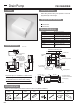
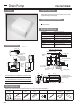
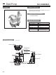
5. Electric wiring
5-1 Set up of the indoor unit
(1)
Remove the panel of indoor unit and the electric box cover.
5-2 Electric wiring
● Route the wiring through the left piping space of the
indoor unit to the electric box as shown in right figure.
● Connect the lead wires to the connectors of the
indoor unit control board, and then place the slack
in the wires in the wiring storage space of the Drain
Pump. (Fix the lead wires with the clamps.)
Wiring storage space
Left piping spaceDrain Pump
Electric
box
Wiring Plate (H)
I.B
X1
Drain Pump
FS
DP
hook
Electric wiring operation
TB
Panel of indoor
unit
CNP
CN4F
Drain Pump PAC-SH94DM-E
185