
Engineering Manual


Wireless Signal Receiver PAR-FA32MA-E
51
TB7 TB3
01
TB5 TB15
02
TB5 TB15
03
TB5 TB15
54
TB7 TB3
06
TB5 TB15
MA
05
TB5 TB15
04
OC IC IC IC
OC IC IC IC
TB5 TB15
CN41
CN40
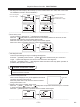
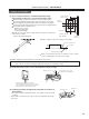
The remote controller wire is connected to CITY MULTI System (C type or later).
(In case of CITY MULTI System)
Group 1 Group 2 Group 3
NOTE: With group operation with a different cooling system, wire only the MA remote controller wiring terminal
block (TB15). Do not wire the indoor/outdoor transmission terminal block (TB5).
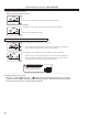
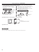
1 Wiring from signal receiving unit.
· Connected to MA remote controller wiring terminal block (TB15) on the indoor unit. (The terminal block has
no polarities.)
2 With group operation (group 3 and group 4 above).
· After wiring the MA remote controller wiring terminal block (TB15) on the group operation indoor unit, connect to the
indoor unit with the lowest address within the group.
3 The signal receiving unit and the MA remote controller may be used together (group 4 above).
· Set the MA remote controller as “Main”, and the signal receiving unit as “Sub”.
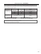
· When other types of remote controllers are used, refer to section “ 7 Possible Combinations of Signal Receiving
Units and Remote Controllers ”.
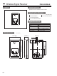
∗ See the installation manual supplied with the outdoor unit for details of setting up indoor (IC) and outdoor (OC) units.
∗ See the relevant equipment manual for details of setting up the central controller and transmission line power supply
unit.
Central management transmission line
(M-NET transmission line)
Indoor and outdoor transmission lines
(M-NET transmission line)
MA remote controller cable
Signal receiving unit
(Main) (Main) (Main)
(Main) (Sub)
Group 4
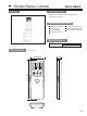
Replace CN41
with CN40.
Leave CN41 as it is.
NOTE:
• No power supply lines are shown and only the trans-
mission lines are shown in the above wiring example.
• Provide shield grounding of M-NET transmission line
at one arbitrary point.
A main remote controller and a sub remote con-
troller can be connected to each group.
Example of System Conguration
255