
Engineering Manual


2-2 Installation of the Drain Pump
3. Installation of refrigerant piping
4. Installation of drain piping
4-1 Connection of drain tube
4-2 Installation of drain piping
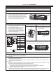
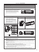
● Fix the Drain Pump on the mounting plate
(1) Install the screws to the 2 upper holes
(indicated by the arrows shown in right figure)
of the mounting plate by hand tightening them about halfway, and then hook
the Drain Pump on the screws.
(2) Level the Drain Pump by using a spirit level. Then tighten the 4 screws se-
curely to fix the Drain Pump.
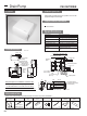
(1) Install the refrigerant piping using the left piping method.
(2) When the refrigerant piping and drain pipe are routed vertically together, route
the piping through the space in the mounting plate.
● Be sure that the indoor unit must be positioned at the place where was
marked at 2-1.
● The bending radius of the refrigerant pipe must be R80 or less.
● The tube raised should be fixed with the pull tight which was put through the
square hole of the mounting plate.
(3) Position the refrigerant piping in the left piping space of the indoor unit as
shown in right figure.
(1) Connect the drain tube (C) which is installed to the left side drain port of the
indoor unit to the drain port of the Drain Pump.
(2) Fix the connection port securely with the tube clip (E) attached.
(3) Connect the flexible drain tube, which is run from the top panel of the Drain
Pump, to the local drain piping. The part connected must be closed by vinyl
chloride type glue.
(4) Insulate the flexible drain tube which is run from top panel of Drain Pump with
the drain tube cover (D) attached.
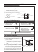
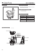
(1) The drain pipe should be installed in accordance with the following procedure.
● The drain pipe should be installed so that the outdoor side (drain side) becomes falling slope (1/100 or more) and do not make
trap or peaks.
● The horizontal run of the drain pipe should be 20 m or less. In case that the tube is crosscut sawing for long distance, some
support brackets should be installed to prevent the pipe from being wavy. Never install the air bleeder. The drain will blow out.
● The hard vinyl chloride pipe VP20 (outer dia. 26 mm) should be used for the drain pipe. And the part connected must be
closed by vinyl chloride type glue to prevent water leak.
● Be sure to wrap the drain pipe with adiabatic material (foam polyethylene: specific gravity 0.03, thickness 9 mm or more)
available on the market.
● Do not install stink trap to the outlet of the drain pipe.
● The outlet of the drain pipe should be installed the place where it is not possible to cause stink.
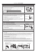
● In case that plural drain pipes are installed, install the main pipe so that it comes approximately 10 cm lower than the drain
outlet and the pipes must be made of material of VP30 or similar and they should be falling slope (1/100 or more).
● It is possible to raise the outlet of the drain pipe to 80 cm (max. lift) from bottom face of Drain Pump. However, if there is a
horizontal run pipe connected to the vertical section of the drain pipe, water will overflow from the drain pan. This is because
too much water will flow back when the operation stops. Therefore, the drain pipe must be raised vertically. Also, install the
flow back stop at the highest point to prevent the water from flow back from horizontal part of the pipe. See the drawing below.
Gas pipe
Liquid pipe
Drain pipe
CAUTION
The Drain Pump must be leveled.
Otherwise, the water leaks and it makes wall dirty.
Tube clip (E)
Drain tube (C)
Make the connection at
the place (mm)
Vinyl chloride pipe for VP20
Commercial elbow joint 3 pcs
Adiabatic material
Supports
1.5~2 m
110
110
10
10
Falling slope 1/100 or more
Drain
Pump
Flow back stop
Air bleeder
Trap, Peaks
<Plural piping example>
Stink trap
Horizontal
run pipe
Drain Pump
Falling slope 1/100 or more
VP20
VP30
80 cm or less
As wide as possible
(10 cm or more)
To Drain Pump
To outlet
(* See the item of refrigerant piping connection in the Installation of the indoor unit.)
Drain Pump PAC-SH94DM-E
184