P-SERIES SPLIT-TYPE, HEAT PUMP AIR CONDITIONERS Air-Conditioners SERVICE MANUAL Series PVA Model name PVA-A30AA4 PVA-A12, 18, 24, 30, 36, 42AA7 PVA-A36AA4 Multi-Position Air Handler PVA-A42AA4 INDOOR UNIT 2015
Contents 1. SAFETY PRECAUTION...................................................................................................................................................... 2 1-1. Always observe for safety.......................................................................................................................................... 2 1-2. Cautions related to new refrigerant.......................................................................................................................
1 SAFETY PRECAUTION 1-1. Always observe for safety Before obtaining access to terminal, all supply circuits must be disconnected. 1-2. Cautions related to new refrigerant Cautions for units utilising refrigerant R410A Use new refrigerant pipes. Do not use refrigerant other than R410A. In case of using the existing pipes for R22, be careful with the followings. · For A36 and A42, be sure to perform replacement operation before test run. · Change flare nut to the one provided with this product.
Unit Gravimeter [3] Service tools Use the below service tools as exclusive tools for R410A refrigerant. No. 1 Tool name Specifications Gauge manifold · Only for R410A · Use the existing fitting specifications. (UNF1/2) · Use high-tension side pressure of 5.3MPa·G or over. 2 Charge hose 3 Electronic scale · Only for R410A · Use pressure performance of 5.09MPa·G or over. 4 Gas leak detector · Use the detector for R134a, R407C or R410A.
(3)Horizontal left (4)Down flow Air inlet Air inlet Air outlet Air outlet INDOOR UNIT INDOOR UNIT 3 SPECIFICATION Service Ref. Power supply (phase, cycle, voltage) Max. Fuse Size Min. Circuit Ampacity External finish Heat exchanger Fan (drive) x No. Fan Fan motor output Fan motor Airflow (Low-Mid-High) External static pressure Operation control & Thermostat 75Pa (0.30 in.WG) Sound pressure level (Low-Mid-High) 125Pa (0.50 in.WG) 200Pa (0.80 in.WG) Drain pipe Dimensions W D H Weight Service Ref.
INDOOR UNIT INDOOR UNIT INDOOR UNIT Service Ref. Power supply (phase, cycle, voltage) Max. Fuse Size Min. Circuit Ampacity External finish Heat exchanger Fan (drive) x No. Fan Fan motor output Fan motor Airflow (Low-Mid-High) External static pressure Operation control & Thermostat 75Pa (0.30 in.WG) Sound pressure level 125Pa (0.50 in.WG) (Low-Mid-High) 200Pa (0.80 in.WG) Drain pipe Dimensions W D H Weight Service Ref. Power supply (phase, cycle, voltage) Max. Fuse Size Min.
INDOOR UNIT Service Ref. Power supply (phase, cycle, voltage) Max. Fuse Size Min. Circuit Ampacity External finish Heat exchanger Fan (drive) x No. Fan Fan motor output Fan motor Airflow (Low-Mid-High) External static pressure Operation control & Thermostat Sound pressure level 75Pa (0.30 in.WG) (Low-Mid-High) 125Pa (0.50 in.WG) 200Pa (0.80 in.WG) Drain pipe Dimensions W D H Weight Specifications are subject to change without notice. PVA-A42AA7 1 phase, 60Hz, 208/230V 15 5.
4 FAN PERFORMANCE AND CORRECTED AIR FLOW MVZ-A12AA4 PVA-A12AA7 • Vertical, Horizontal Right, Horizontal Left External static pressure 0.30 [in.WG] (75Pa) 208/230V 60Hz Static pressure (Pa)[in.WG] 75 [0.30] 100 [0.40] Middle 50 [0.20] External static pressure 0.30 [in.WG] (75Pa) 208/230V 60Hz 75 [0.30] High Static pressure (Pa)[in.WG] 100 [0.40] • Downflow Low 25 [0.10] High 50 [0.20] Middle Low 25 [0.
MVZ-A24AA4 PVA-A18AA7 • Vertical, Horizontal Right, Horizontal Left 100 [0.40] External static pressure 0.30 [in.WG] (75Pa) 208/230V 60Hz 75 [0.30] 100 [0.40] 50 [0.20] Middle Low 25 [0.10] 15 [530] 20 [706] 0 [0] 13 [459] 24 [847] High 50 [0.20] 25 [0.10] 0 [0] 13 [459] External static pressure 0.30 [in.WG] (75Pa) 208/230V 60Hz 75 [0.30] High Static pressure (Pa)[in.WG] Static pressure (Pa)[in.WG] • Downflow Middle Low 15 [530] Airflow rate (m3/min)[cfm] 150 [0.
MVZ-A30AA4 PVA-A24AA7 • Vertical, Horizontal Right, Horizontal Left 100 [0.40] • Downflow External static pressure 0.30 [in.WG] (75Pa) 208/230V 60Hz 100 [0.40] External static pressure 0.30 [in.WG] (75Pa) 208/230V 60Hz High High 75 [0.30] Static pressure (Pa)[in.WG] Static pressure (Pa)[in.WG] 75 [0.30] Middle 50 [0.20] Low 50 [0.20] Middle Low 25 [0.10] 25 [0.10] 0 [0] 15 [530] 20 [706] 25 [883] 0 [0] 15 [530] 29 [1024] 20 [706] Airflow rate (m3/min)[cfm] 150 [0.
PVA-A30AA4 PVA-A30AA7 • Vertical, Horizontal Right, Horizontal Left 100 [0.40] • Downflow External static pressure 0.30 [in.WG] (75Pa) 208/230V 60Hz 100 [0.40] High 75 [0.30] High 50 [0.20] Static pressure (Pa)[in.WG] Static pressure (Pa)[in.WG] 75 [0.30] External static pressure 0.30 [in.WG] (75Pa) 208/230V 60Hz Middle Middle 50 [0.20] Low Low 25 [0.10] 25 [0.10] 0 [0] 15 [530] 20 [706] 25 [883] 0 [0] 15 [530] 29 [1024] 20 [706] Airflow rate (m3/min)[cfm] 150 [0.
PVA-A36AA4 PVA-A36AA7 • Vertical, Horizontal Right, Horizontal Left 100 [0.40] • Downflow External static pressure 0.30 [in.WG] (75Pa) 208/230V 60Hz 100 [0.40] 75 [0.30] High 50 [0.20] Static pressure (Pa)[in.WG] Static pressure (Pa)[in.WG] 75 [0.30] External static pressure 0.30 [in.WG] (75Pa) 208/230V 60Hz Middle High 50 [0.20] Middle Low Low 25 [0.10] 25 [0.10] 0 [0] 20 [706] 25 [883] 30 [1059] 35 [1236] 0 [0] 20 [706] 37 [1306] 25 [883] Airflow rate (m3/min)[cfm] 150 [0.
PVA-A42AA4 PVA-A42AA7 • Vertical, Horizontal Right, Horizontal Left 100 [0.40] • Downflow External static pressure 0.30 [in.WG] (75Pa) 208/230V 60Hz 125 [0.50] 100 [0.40] 75 [0.30] High High 50 [0.20] Static pressure (Pa)[in.WG] Static pressure (Pa)[in.WG] External static pressure 0.30 [in.WG] (75Pa) 208/230V 60Hz Middle 75 [0.30] Middle 50 [0.20] Low Low 25 [0.10] 25 [0.
PVA-A12, 18, 24, 30, 36, 42AA7 Air Filter Power Source: 60Hz, 208/230V 25 [0.100] External static pressure (Pa) [In.WG] 20 [0.080] 15 [0.060] 10 [0.040] 5 [0.020] 0 [0] 0 [0] 10 [353] 20 [706] 30 [1059] 40 [1412] 50 [1766] Airflow rate (m3/min)[CFM] Specifications are subject to change without notice. 13 © 2016 Mitsubishi Electric US, Inc.
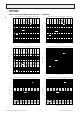
5 SOUND PRESSURE LEVELS 5-1. Sound pressure level Multi-Position 5-2. NC curves PVA-A18AA7 PVA-A12AA7 Specifications are subject to change without notice. 14 © 2016 Mitsubishi Electric US, Inc.
PVA-A24AA7 Specifications are subject to change without notice. PVA-A30AA7 15 © 2016 Mitsubishi Electric US, Inc.
PVA-A36AA7 Specifications are subject to change without notice. PVA-A42AA7 16 © 2016 Mitsubishi Electric US, Inc.
OUTLINES & DIMENSIONS 6 INDOOR UNIT PVA-A12, 18, 24, 30, 36, 42AA7 Left side Left side view view Model Model Model PVA-A12AA7 P VA-A30AA4 PVA-A30AA4 PVA-A18AA7 PVA-A24AA7 P VA-A36AA4 PVA-A36AA4 PVA-A30AA7 P VA-A42AA4 PVA-A36AA7 PVA-A42AA4 PVA-A42AA7 A A 77.8(3-1/8) 77.8(3-1/8) E F 3 Top view 43(1-3/4) 43(1-3/4) 92(3-5/8) 92(3-5/8) E 55(2-3/16) 55(2-3/16) Air filter H Bottom view G 792 D 953.5 953.
Unit:mm(in.) 609.6(24) Length of Unit Horizontal Installation Width of Unit Vertical Installation 609.6(24) 609.6(24) Clearance Area 609.6(24) Specifications are subject to change without notice. 18 © 2016 Mitsubishi Electric US, Inc.
7 WIRING DIAGRAM PVA-A12, 18, 24, 30, 36, 42AA7 TRANSMISSION WIRES DC 12V RFI INSIDE SECTION OF CONTROL BOX TB15 1 2 TB6 1 2 R.B. TB4 I.B. LED2 SW2 OFF ON CN41 SWE (BLUE) 2 CN22 1 CN51 MVZ-A36AA4 12345 SW5 SW5 SW2 SW2 SW1 U ZNR02 MS 3~ 12345 ON SW5 12345 12345678 ON P.B.
8 REFRIGERANT SYSTEM DIAGRAM PVA-A12, 18, 24, 30, 36, 42AA7 Strainer (#50) Heat exchanger Refrigerant GAS pipe connection (Flare) Thermistor TH5 (Cond./ Eva.temperature) Refrigerant flow in cooling Refrigerant flow in heating Thermistor TH2 Pipe temperature(Liquid) Refrigerant LIQUID pipe connection (Flare) Thermistor TH1 (Room temperature) Distributor with strainer (#50) Strainer (#50) 16 Specifications are subject to change without notice. 20 © 2016 Mitsubishi Electric US, Inc.
9 HEATER CONTROL 9-1. Control Specifications And Function Setting • Table 1 shows the mode setting for the field-installed heater. Table. 1 [Function Table] Select unit numbers 01 to 03 or all units (AL [wired remote controller] / 07 [IR wireless remote controller]) Mode (function ) No.
• Table 3 shows how the time delay is selected Table. 3 [Time Delay Selection Table] Request Code *1 Action *3 390 Monitor Time Delay Setting 391 Set Time Delay to 14 minutes 392 Set Time Delay to 19 minutes 393 Set Time Delay to 24 minutes *2 394 Set Time Delay to 29 minutes *1 Time delay can only be selected with MA controller. If use of a non-MA controller is desired, the time delay must first be selected with the MA controller. Then the non-MA controller can be attached and used.
9-2. Fan control By setting the Mode No. 23 in the Function Table in section 9-1 and using CN4Y from the CN24RELAY-KIT-CM3 kit, the following patters of fan control will become possible. By setting the Mode No. 23 in the Function Table in section 9-1, the following patterns of fan control will become possible.
9-3. CN24RELAY-KIT-CM3 (Optional Parts) installation The6-3. following section describes installation the External Heater Adapter that connects to PVA-A AA7 PAC-YU25HT (Optional Parts) ofinstallation series indoor unit. This products is the special wiring parts to drive an electric heater with the air conditioner. The following section describes installation of the External Heater Adapter that connects to PEA-A AA (1) Parts list series indoor unit.
CN4Y for FAN control (CN24RELAY-KIT-CM3) (3) Locally procured wiring A basic connection method is shown below. Remote control board Relay circuit Relay circuit White 2 X Adapter X Indoor unit control board CN24 Electric Heater or panel heater Red 1 White 2 X X White Remote control board 1 White 1cable length Maximum is 10 m (32ft) Preparations in the field Electric Heater or panel heater 3 CN4Y White Electric Heater power source A basic connection method is shown below.
10 HUMIDIFIER CONTROL 10-1. Control Specifications The below table shows how the field installed humidifier and fan speed is controlled. Mode (function) No.
11 ERV (ENERGY RECOVERY VENTILATION) CONTROL 11-1. Control Specifications The how the field installed E ERV R V isiscontrolled. Thebelow belowtable tableshows shows how the field installed controlled.
12 TROUBLESHOOTING 12 TROUBLESHOOTING 12-1. CAUTIONS ON TROUBLESHOOTING (1) Before troubleshooting, check the followings: 12-1. Cautions on troubleshooting Beforethe troubleshooting, check the followings: 1(1)Check power supply voltage. 1 Check power supply voltage. 2 Check thethe indoor/outdoor connecting wire for mis-wiring. 2 Check the followings indoor/outdoor connecting wire for mis-wiring. (2) Take care the during servicing. (2) Take care the followings during servicing.
12-2. Self-check function • Refer to the installation manual that comes with each remote controller for details. • RF thermostat is not established.
For description of each LED (LED1, 2, 3) provided on the indoor controller, refer to the following table. LED 1 (power for microcomputer) Indicates whether control power is supplied. Make sure that this LED is always lit. LED 2 (power for remote controller) Indicates whether power is supplied to the remote controller. This LED lights only in the case of the indoor unit which is connected to the outdoor unit refrigerant address “0”.
Note: Refer to the manual of outdoor unit for the details of display such as F, U, and other E. 12-3. Self-diagnosis action table Error Code P1 Abnormal point and detection method Room temperature thermistor (TH1) 1 The unit is in three-minute resume prevention mode if short/open of thermistor is detected. Abnormal if the unit does not reset normally after three minutes. (The unit returns to normal operation, if it has normally reset.
Error Code Abnormal point and detection method Freezing/overheating protection is working 1 Freezing protection (Cooling mode) The unit is in six-minute resume prevention mode if pipe temperature stays under -15:[5˚F] for three minutes after the compressor started. Abnormal if it stays under -15:[5˚F] for three minutes again within 16 minutes after six-minute resume prevention mode.
Error Code P9 E0 or E4 Abnormal point and detection method Abnormality of pipe temperature thermistor / Condenser-Evaporator (TH5) 1 The unit is in three-minute resume protection mode if short/open of thermistor is detected. Abnormal if the unit does not get back to normal within three minutes. (The unit returns to normal operation, if it has normally reset.
Error Code E6 E7 Abnormal point and detection method Indoor/outdoor unit communication error (Signal receiving error) 1 Abnormal if indoor controller board cannot receive any signal normally for six minutes after turning the power on. 2 Abnormal if indoor controller board cannot receive any signal normally for three minutes.
12-4. Troubleshooting by inferior phenomena Phenomena (1)LED2 on indoor controller board is off. Note: Refer to the manual of outdoor unit for the detail of remote controller. Cause • When LED1 on indoor controller board is also off. 1 Power supply of rated voltage is not supplied to outdoor unit. 2 Defective outdoor controller circuit board 3 Power supply of 208~230V is not supplied to indoor unit. 4 Defective indoor controller board (2)LED2 on indoor controller board is blinking.
12-5. Test point diagram 12-5-1. Power supply board PVA-A12AA7 PVA-A18AA7 PVA-A24AA7 PVA-A30AA7 PVA-A36AA7 PVA-A42AA7 CND CND Power supply voltage (208 - 230VAC) CNMF Fan motor output 1 - 4: 310 - 340 VDC 5 - 4: 15 VDC 6 - 4: 0 - 6.5 VDC 7 - 4: Stop 0 or 15 VDC Run 7.
12-5-2.
12-6. Trouble criterion of main parts PVA-A12AA7 PVA-A30AA7 PVA-A18AA7 PVA-A36AA7 PVA-A24AA7 PVA-A42AA7 Part name Check method and criterion Room temperature thermistor (TH1) Measure the resistance with a tester. (Part temperature 10C (50F) ~ 30C (86F)) Pipe temperature thermistor/liquid (TH2) Condenser/evaporator temperature thermistor (TH5) Normal Abnormal 4.3k~9.
12-8. DC MOTOR (FAN MOTOR/INDOOR CONTROLLER BOARD) 12-8. DC FAN Fan motor (FAN MOTOR/INDOOR CONTROLLER BOARD) Check method of DC fan motor (fan motor/indoor controller circuit board) 1 Notes · High voltage is applied to the connecter (CNMF) for the fan motor. Give attention to the service. · Do not pull out the connector (CNMF) for the motor with the power supply on. (It causes trouble of the indoor controller circuit board and fan motor.) 2 Self check Symptom : The indoor fan cannot turn around.
12-9.
13 DISASSEMBLY PROCEDURE 13-1. Control box Exercise caution when removing heavy parts. 1. Remove the Electric panel (2 screws) Fig. 1 Specifications are subject to change without notice. 41 © 2016 Mitsubishi Electric US, Inc.
13-2. Thermistor (Return Air) Exercise caution when removing heavy parts. 1. Remove the Filter panel (2 thumbscrews). 2. Remove the Blower panel (2 screws). Fig. 3 w() MITSUBISHI ELECTRIC CORPORATIO DIM.mm 2 3. Remove the cover over the Return Air thermistor box and unplug the thermistor. 4. Pull out the thermistor holder and thermistor inside the box. 3 4 5 6 7 DATE SCALE DRAWN 1:15 CHECKED NTS DESIGNED 8 9 10 11 12 13 Fig. 4 Specifications are subject to change without notice.
C D DETAIL A 13-3. Coil Assembly E Exercise caution when removing heavy parts. 1. Remove the Electrical, Blower and Filter panel indicated in sections 1 and 2. 2. Remove the Coil panel by removing all of the screws securing it to the (3) smaller panels for refrigerant and drain lines. F DETAIL B G H I Fig. 5 CHANGE Creo : 0_TOP_ASSY_L_21554B2.drw ( ) J 3. Slide the smaller panels in the directions indicated and remove.
5. Remove the plate covering the coil assembly to access the thermistors. Fig. 9 6. Remove lower and side drain pan. Fig. 10 Specifications are subject to change without notice. 44 © 2016 Mitsubishi Electric US, Inc.
13-4. Blower/Fan Assembly Exercise caution when removing heavy parts. 1. Remove the Blower and Filter panel (along with filter if installed) indicated in section 2. 2. Remove the (1 or 2) brackets that secure the coil assembly. Fig. 11 3. Remove the door that covers the small enclosure attached to the fan assembly (Fig.12). Unplug the motor and route the wire harness out of the enclosure. 4. Remove the (2) screws that secure the fan assembly and slide out. Fig.
This product is designed and intended for use in the residential, commercial and light-industrial environment. Please be sure to put the contact address/telephone number on this manual before handing it to the customer. MITSUBISHI ELECTRIC US, INC. www.mitsubishielectric-usa.com Toll Free: 800-433-4822 MEUS DOC# MD-1404-K011, December 2016 Specifications are subject to change without notice. © 2016 Mitsubishi Electric US, Inc.