
Indoor Service Manual
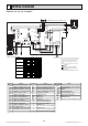
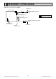
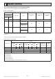
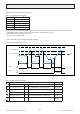
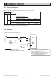
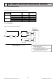
Table Of Contents
- Cover
- Contents
- 1. SAFETY PRECAUTION
- 2. PART NAMES AND FUNCTIONS
- 3. SPECIFICATION
- 4. FAN PERFORMANCE AND CORRECTED AIR FLOW
- 5. SOUND PRESSURE LEVELS
- 6. OUTLINES & DIMENSIONS
- 7. WIRING DIAGRAM
- 8. REFRIGERANT SYSTEM DIAGRAM
- 9. HEATER CONTROL
- 10. HUMIDIFIER CONTROL
- 11. ERV (ENERGY RECOVERY VENTILATION) CONTROL
- 12. TROUBLESHOOTING
- 12-1. Cautions on troubleshooting
- 12-2. Self-check function
- 12-3. Self-diagnosis action table
- 12-4. Troubleshooting by inferior phenomena
- 12-5. Test point diagram
- 12-6. Trouble criterion of main parts
- 12-7. Thermistor
- 12-8. DC Fan motor (FAN MOTOR/INDOOR CONTROLLER BOARD)
- 12-9. Functions of dip switch and jumper wire
- 13. DISASSEMBLY PROCEDURE
- Back Cover

Specications are subject to change without notice. © 2016 Mitsubishi Electric US, Inc.
20
8 REFRIGERANT SYSTEM DIAGRAM
PVA-A12, 18, 24, 30, 36, 42AA7
16
Thermistor TH2
Pipe temperature(Liquid)
Distributor
with strainer (#50)
Thermistor TH5
(Cond./ Eva.temperature)
Thermistor TH1
(Room temperature)
Refrigerant flow in cooling
Refrigerant flow in heating
Strainer (#50)
Strainer (#50)
Heat exchanger
Refrigerant GAS pipe connection
(Flare)
Refrigerant LIQUID pipe connection
(Flare)