
Indoor Service Manual
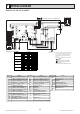
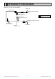
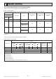
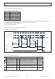
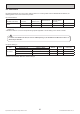
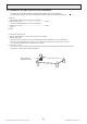
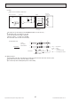
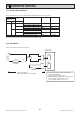
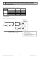
Table Of Contents
- Cover
- Contents
- 1. SAFETY PRECAUTION
- 2. PART NAMES AND FUNCTIONS
- 3. SPECIFICATION
- 4. FAN PERFORMANCE AND CORRECTED AIR FLOW
- 5. SOUND PRESSURE LEVELS
- 6. OUTLINES & DIMENSIONS
- 7. WIRING DIAGRAM
- 8. REFRIGERANT SYSTEM DIAGRAM
- 9. HEATER CONTROL
- 10. HUMIDIFIER CONTROL
- 11. ERV (ENERGY RECOVERY VENTILATION) CONTROL
- 12. TROUBLESHOOTING
- 12-1. Cautions on troubleshooting
- 12-2. Self-check function
- 12-3. Self-diagnosis action table
- 12-4. Troubleshooting by inferior phenomena
- 12-5. Test point diagram
- 12-6. Trouble criterion of main parts
- 12-7. Thermistor
- 12-8. DC Fan motor (FAN MOTOR/INDOOR CONTROLLER BOARD)
- 12-9. Functions of dip switch and jumper wire
- 13. DISASSEMBLY PROCEDURE
- Back Cover

Specications are subject to change without notice. © 2016 Mitsubishi Electric US, Inc.
27
ERV (ENERGY RECOVERY VENTILATION) CONTROL
11
The below table shows how the field installed ERV is controlled.
A basic connection method is shown below.
ERV output ConditionFan speed CN2Coutput
(=Fan output)
CNER input
OFFCool/Heat/Fan operation RC settin
g
ON
DefrostSTOPOFF
STOP STOP OFF
ON Cool/Heat/Fan operation RC settingON
DefrostSTOPOFF
STOP LowON
XB
XF
ERV
ERV switch
XB
On-site preparation
Maximum cable length is 10m(32ft)
CNER
CN2C
Indoor unit
controlboard
ERV
power source
Use XB relay having following specifications
Rated voltage:12VDC
Power consumption:1W or less
ERV switch:Minimum applicable load 1mA at DC
Contact rating voltage:15VDC or more
Contact rating current:0.1A or more
11-1. Control Specifications
11-2. Installation
The below table shows how the field installed E R V is controlled.
A bas ic connection method is shown below.
E R V output
C ondition
F an speed
C N2C output
(=F an output)
C NE R input
OF F
C ool/Heat/Fan operation
R C setting
ON
Defros t
S TOP
OF F
S TOP
S TOP
OF F
ON
C ool/Heat/Fan operation
R C setting
ON
Defros t
S TOP
OF F
S TOP
ON
XB
XF
E R V
E R V s witch
XB
On-s ite preparation
Maximum cable length is 10m(32ft)
C NE R
C N2C
Indoor unit
control board
E R V
power source
Use XB relay having following specifications
R ated voltage:12V DC
Power consumption:1W or less
E R V s witch:Minimum applicable load 1mA at DC
C ontact rating voltage:15VDC or more
C ontact rating current:0.1A or more
S TOP