
Service Manual

16
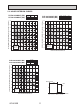
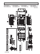
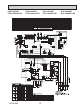
OCH636B
Unit: mm<in>
PUZ-A36NKA7 PUZ-A42NKA7 PUY-A36NKA7 PUY-A42NKA7
PUZ-A36NKA7-BS PUZ-A42NKA7-BS PUY-A36NKA7-BS PUY-A42NKA7-BS
Bottom piping hole
(Knockout)
Drain hole
(5-ø33<1-5/16>)
154
<6-1/16>
136
<5-11/32>
81 <3-3/16>
45 <1-25/32>
110 <14-11/32>
160
<6-5/16>
160
<6-5/16>
160
<6-5/16>
86 <3-3/8>
Rear Air Intake
Handle for
moving
Handle for
moving
Side Air Intake
1
2
Handle for moving
Handle for
moving
Service panel
Earth terminal
Terminal connection
Left
...
Power supply wiring
Right
...
Indoor/Outdoor wiring
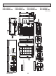
*1 442 <17-2/5>
1063 <41-7/8>
632 <24-7/8>
*1 450 <17-23/32>
26 <1-1/32>
369 <14-17/32>
1338 <52-11/16>
362 <14-1/4>
1050 <41-11/32>
Air intake
Front piping cover
Rear piping cover
2-12×36 Oval holes
(Foundation Bolt M10<W3/8>)
Installation Feet
2-U Shaped notched holes
(Foundation Bolt M10<W3/8>)
225 <8-27/32>
42 <1-21/32>
60 <2-3/8>
25 <31/32>
330 <13>
225 <8-27/32>
600 <23-5/8>
70 <2-3/4>
417 <16-13/32>
28 <1-3/32>
370 <14-9/16>
19 <3/4>
40
<1-9/16>
53 <2-3/32>
56 <2-7/32>
0
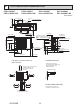
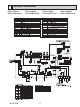
Conduit hole
( ø 24<15/16>knockout)
Conduit hole
( ø 37<1-15/32>knockout)
Rear trunking hole
(Knockout)
Rear piping hole
(Knockout)
75 <2-15/16>
92 <3-5/8>
73 <2-7/8>
60 <2-3/8>
5<3/16>
26
<1-1/32>
27
<1-1/16>
55 <2-3/16>
55 <2-3/16> 60 <2-3/8>
ø 92
<3-5/8>
Conduit hole
( ø 24<15/16>knockout)
Front piping hole
(Knockout)
Front trunking hole
(Knockout)
Conduit hole
( ø
37<1-15/32>knockout)
26
<1-1/32>
92 <3-5/8>
27
<1-1/16>
55 <2-3/16>
73 <2-7/8>
75 <2-15/16>
55 <2-3/16>60 <2-3/8>
ø 92
<3-5/8>
Right trunking hole
(Knockout)
Conduit hole
( ø 37<1-15/32>knockout)
Conduit hole
( ø 24<15/16>knockout)
Right piping hole
(Knockout)
73
<2-7/8>
61 <2-3/8>
5<3/16>
29 <1-5/32>
27 <1-1/16>26
<1-1/32>
92
<3-5/8>
53 <2-3/32> 60 <2-3/8>
55 <2-3/16>
92 <3-5/8>
ø 92
<3-5/8>
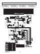
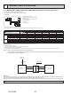
Min.
Min.
Min. Min.
Service space
Min.
150
<5-29/32>
500
<19-11/16>
500
<19-11/16>
15 <3/5>
50
<2>
Max.
30 <1-3/16>
( )
2
1
...
Refrigerant GAS pipe connection (FLARE)
ø15.88(5/8F)
...
Refrigerant LIQUID pipe connection (FLARE)
ø9.52(3/8F)
*1
...
Indication of STOP VALVE connection location.
Piping Knockout Hole Details
Example of Notes
FREE
Min. 15mm
<3/5>
Min. 15mm
<3/5>
Min. 1000mm
<39-3/8>
Min. 150mm
<5-29/32>
Piping and wiring connections
can be made from 4 directions:
FRONT, Right, Rear and Below.
4
PIPING-WIRING DIRECTIONS
3 FOUNDATION BOLTS
2 SERVICE SPACE
1 FREE SPACE (Around the unit)
Please secure the unit firmly
with 4 foundation (M10<W3/8>) bolts.
(Bolts and washers must be
purchased locally.)
Dimensions of space needed
for service access are
shown in the below diagram.
The diagram below shows a basic example.
Explanation of particular details are
given in the installation manuals etc.
<Foundation bolt height>
Air Discharge
Rear Air Intake
Side Air Intake
1/2 Conduit
attachment
ø 22.2<7/8>
ø 27.8<1-3/32>
When installing the conduit.
Set the attachment to the
inner side of each panel.
3/4 Conduit
attachment
Scale 1:5
60 <2-3/8> 22.5 <7/8>
5<3/16>
24.7 <31/32>
100
<3-15/16>
FOUNDATION