
Submittal
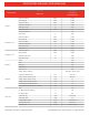

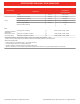

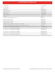
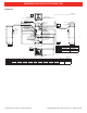
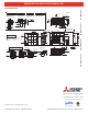
Table Of Contents

PVA-A30AA7
Specications are subject to change without notice. © 2016 Mitsubishi Electric US, Inc.
17
6 OUTLINES & DIMENSIONS
INDOOR UNIT
PVA-A12, 18, 24, 30, 36, 42AA7
(18-3/16)
(20X24X1) (22-13/16X15-7/8)
(31-3/16)
(18-13/16) (15-1/8) (10-1/2) (54-1/4) (29-1/16) (37-9/16)
(25) (22-13/16) (19-1/8) (12-1/2) (31-7/16) (41-1/2) (33-5/8) (22-3/16)
(21)
(20X20X1) (18-13/16X15-7/8)
Model ABCDEFGHJ
Gas pipe Liquid pipe
PVA-A30AA4
477 382.6 266.5 1378 737 953.5
PVA-A36AA4
635 579 484.6 317.5
1511
(59-1/2)
798.5 1053 853.5 563
PVA-A42AA4
Model
Nominal Filter size
Duct Connection
PVA-A30AA4
PVA-A36AA4
PVA-A42AA4
(5/8) (3/8)
461
534
508X609.6X25.4
508X508X25.4
579X402
477X402
J
77.8(3-1/8)
66(2-5/8)
36.8(1-1/2)
43(1-3/4) 8(3/8)
92(3-5/8) 30(1-3/16)
43(1-3/4)
8(3/8)
55(2-3/16)
548(21-5/8)
117.4 (4-5/8)
402(15-7/8)
B(Duct)
28.8(1-3/16)
76(3)
C
A
D
525.5(20-3/4)50.8(2)470(18-9/16)
H
55(2-3/16)
G
70(2-13/16)
8(3/8)
F
55(2-3/16)
E
24(15/16)
13.2(9/16)
Control box
Air filter
Air outlet
Air inlet
(Duct)
Refrigerant piping
brazing connection(gas)
Refrigerant piping
brazing connection(liquid)
Primary drain pipe
(Gravity drain)
ø19.05(3/4) 3/4"FPT
Secondary drain pipe
(Emergency draining)
ø19.05(3/4) 3/4"FPT
Primary drain pipe
(Gravity drain)
ø19.05(3/4) 3/4"FPT
(Horizontal left)
(Horizontal Right)
Secondary drain pipe
(Emergency draining)
ø19.05(3/4) 3/4"FPT
Primary drain pipe
(Gravity drain)
ø19.05(3/4) 3/4"FPT
Secondary drain pipe
(Emergency draining)
ø19.05(3/4) 3/4"FPT
Terminal block
(Indoor / Outdoor unit connection)
Terminal block
(Remote controller transmission)
2-ø4.6 Burring Holes
for electric heat installation
ø26 Knockout Hole
(Remote controller transmission)
ø26 Knockout Hole
ø26 Knockout Hole
ø26 Knockout Hole
(Indoor / Outdoor unit connection)
(Indoor /Outdoor
unit connection)
(Remote controller transmission)
792
Ø15.88 Ø9.52
Note 1.Keep the service space for maintenance at the front.
Unit:mm(in.)
Top
Top
view
Front
Bottom
Bottom
view
view
Left side
view
Right side
view
1
3
3
2
1
2
Model
Nominal Filter Size
Duct Connection
PVA-A12AA7 508 x 406.4 x 25.4
(20 x 16 x 1)
376 x 402
(14-13/16 x 15-7/8)
PVA-A18AA7
PVA-A24AA7 508 x 508 x 25.4
(20 x 20 x 1)
477 x 402
(18-13/16 x 15-7/8)
PVA-A30AA7
PVA-A36AA7 508 x 609.6 x 25.4
(20 x 24 x 1)
579 x 402
(22-13/16 x 15-7/8)
PVA-A42AA7
Unit: mm (in.)
Model A B C D E F G H J
Gas Pipe
Liquid Pipe
PVA-A12AA7
432 (17) 376 (14-13/16) 281 (11-1/8) 224 (8-7/8) 1275 (50-1/4) 680 (26-13/16) 823 (32-7/16) 735.5 (29) 360 (14-3/16) Φ 12.7 (1/2) Φ 6.35 (1/4)
PVA-A18AA7
PVA-A24AA7
534 (21) 477 (18-13/16) 382.6 (15-1/8) 266.5 (10-1/2) 1378 (54-1/4) 737 (29-1/16) 953.5 (37-9/16) 792 (31-3/16) 461 (18-3/16)
Φ 15.88 (5/8) Φ 9.52 (3/8)
PVA-A30AA7
PVA-A36AA7
635 (25) 579 (22-13/16) 484.6 (19-1/8) 317.5 (12-1/2) 1511 (59-1/2) 798.5 (31-7/16) 1053 (41-1/2) 853.5 (33-5/8) 563 (22-3/16)
PVA-A42AA7
(18-3/16)
(20X24X1) (22-13/16X15-7/8)
(31-3/16)
(18-13/16) (15-1/8) (10-1/2) (54-1/4) (29-1/16) (37-9/16)
(25) (22-13/16) (19-1/8) (12-1/2) (31-7/16) (41-1/2) (33-5/8) (22-3/16)
(21)
(20X20X1) (18-13/16X15-7/8)
Model A B C D E F G H J
Gas pipe Liquid pipe
P VA-A30AA4
477 382.6 266.5 1378 737 953.5
P VA-A36AA4
635 579 484.6 317.5
1511
(59-1/2)
798.5 1053 853.5 563
P VA-A42AA4
Model
Nominal Filter si ze
Duct Connection
P VA-A30AA4
P VA-A36AA4
P VA-A42AA4
(5/8) (3/8)
461
534
508X609.6X25.4
508X508X25.4
579X402
477X402
J
77.8(3-1/8)
66(2-5/8)
36.8(1-1/2)
43(1-3/4) 8(3/8)
92(3-5/8) 30(1-3/16)
43(1-3/4)
8(3/8)
55(2-3/16)
548(21-5/8)
117.4 (4-5/8)
402(15-7/8)
B(Duct)
28.8(1-3/16)
76(3)
C
A
D
525.5(20-3/4)50.8(2)470(18-9/16)
H
55(2-3/16)
G
70(2-13/16)
8(3/8)
F
55(2-3/16)
E
24(15/16)
13.2(9/16)
Control b ox
Air filter
Air outlet
Air inlet
(Duct)
Ref rigerant piping
are connection(gas)
Ref rigerant piping
are connection(liquid)
P rimary drain pipe
(G ravity drain)
ø19.05(3/4) 3/4"FPT
Seconda ry d rain pipe
(Emergency d raining)
ø19.05(3/4) 3/4"FPT
P rimary drain pipe
(G ravity drain)
ø19.05(3/4) 3/4"FPT
(Ho rizontal left)
(Ho rizontal Right)
Seconda ry drain pipe
(Emergency d raining)
ø19.05(3/4) 3/4"FPT
P rimary drain pipe
(G ravity drain)
ø19.05(3/4) 3/4"FPT
Seconda ry drain pipe
(Emergency d raining)
ø19.05(3/4) 3/4"FPT
Terminal block
(Indoor / Outdoor unit connection)
Terminal block
(Remote controller t ransmission)
2-ø4.6 Bur ring Holes
for elect ric heat installation
ø26 Kno ckout Hole
(Remote controller t ransmission)
ø26 Kno ckout Hole
ø26 Kno ckout Hole
ø26 Kno ckout Hole
(Indoor / Outdoor unit connection)
(Indoor /Outdoor
unit connection)
(Remote controller t ransmission)
792
Ø15.88 Ø9.52
Note 1. K eep the se rvice space for maintenance at the front .
Unit:mm(in.)
Top
Top
view
Front
Bottom
Bottom
view
view
Left side
view
Right side
view
1
3
3
2
1
2
DIMENSIONS: PVA-A30AA7 & PUZ-A30NHA7 (-BS)
Specifications are subject to change without notice. © 2018 Mitsubishi Electric Trane HVAC US LLC. All rights reserved.