
Submittal
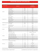

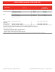

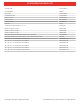
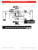
Table Of Contents

PUZ-A30NHA7(-BS)
15
PUZ-A24NHA7 PUZ-A30NHA7 PUY-A24NHA7 PUY-A30NHA7
PUZ-A24NHA7-BS PUZ-A30NHA7-BS PUY-A24NHA7-BS PUY-A30NHA7-BS
Drain hole
(5- ø33<1-5/16>)
Bottom piping hole
(knockout)
145
<5-23/32>
145
<5-23/32>
145
<5-23/32>
220
<8-21/32>
30 <1-3/16>
81<3-3/16> 219 <8-5/8>
71<2-13/16>
71
<2-13/16>
Rear piping cover
Front piping cover
2-12×36 oval holes
(Foundation Bolt M10<W3/8>)
Air Discharge
Rear Air Intake
Side Air Intake
2-U Shaped notched holes
(Foundfation Bolt M10<W3/8>)
Installation Feet
330 <13>
175<6-7/8>
57<2-1/4>
41 <1-5/8>
417 <1-1/32>
28<1-3/32> 370<14-9/16>
19<3/4>
25 <31/32>
70 <2-3/4>
175 <6-7/8> 600<23-5/8>
40<19/32>
53<2-3/32>
61<2-13/32>
0
Side Air Intake
Handle
for moving
Air Intake
Rear Air Intake
Handle for
moving
Min.100mm
<3-15/16>
Min. 500mm
<19-11/16>
2
1
Handle
for moving
Handle for moving
Service panel
Earth terminal
Left
...
Power supply wiring
Reight
...
Indoor/Outdoor wiring
Terminal Connections
669<26-11/32>
950 <37-13/32>
322<12-11/16>
943 <37-1/8>
473 <18-5/8>
23 <29/32>
*1 447<17-5/8>
*1 431<16-31/32>
Min. 10mm
<3/8>
Min. 10mm
<3/8>
FREE
When installing the conduit,
Set the attachment to the
inner side of each panel.
1/2 Conduit attachment
2-ø22.2<7/8>
31<1-7/32>
74<2-19/32>
40<1-9/16>
2
1
...
Refrigerant GAS pipe connection (FLARE) ø15.88(5/8F)
...
Refrigerant LIQUID pipe connection (FLARE) ø 9.52(3/8F)
*1
...
Indication of STOP VALVE connection location.
Example of Notes
Power supply wiring hole
(2- ø27<1-1/16>knockout)
Rear trunking hole
(knockout)
Rear piping hole
(knockout)
63 <2-1/2>
73 <2-7/18>
23 <29/32>
55 <2-3/16>
27<1-1/16>
92<3-5/18>
65 <2-9/16>
45<1-25/32> 40<1-9/16>
ø
92 <3-5/8>
Power supply wiring hole
(2-ø27knockout)
Front trunking hole
(knockout)
Front piping hole
(knockout)
45<1-25/32>
65<2-9/16>
92<3-5/8>
40<1-9/16>
63<2-1/2>
23 <29/32> 73 <2-7/8>
55<2-3/16>
27<1-1/16>
92
<3-5/8>
Right piping hole
(knockout)
Right trunking hole
(knockout)
Power supply wiring hole
(2- ø27knockout)
19<3/4> 55 <2-3/16>
23 <29/32>
27
<1-1/16>
92 <3-5/8>
92 <3-5/8>
40<1-9/16>75 <2-31/32>
73 <2-7/18> 63 <2-1/2>
92
<3-5/8>
Piping knockout Hole Details
Max.
<Foundation bolt height>
30 <1-3/16>
Min.
Min.
Service
space
10 <13>
Min.
500 <19-11/16>
500 <19-11/16>
100 <3-15/16>
Min.
Dimensions of space needed
for service access are
shown in the below diagram.
Please secure the unit firmly
with 4 foundation (M10<W3/8>) bolts.
(Bolts and washers must be
purchased locally.)
Piping and wiring connections
can be made from 4 directions:
FRONT,Right,Rear and Below.
4 PIPING-WIRING DIRECTIONS
3 FOUNDATION BOLTS2 SERVICE SPACE
1 FREE SPACE (Around the unit)
The diagram below shows a
basic example.
Explantion of particular details are
given in the installation manuals etc.
ø
ø
FOUNDATION
OCH636
Unit: mm<in>
FORM# PVA-A30AA7 / PUZ-A30NHA7(-BS) - 201810
1340 Satellite Boulevard, Suwanee, GA 30024
Toll Free: 800-433-4822 www.mehvac.com
DIMENSIONS: PVA-A30AA7 & PUZ-A30NHA7 (-BS)
Specifications are subject to change without notice. © 2018 Mitsubishi Electric Trane HVAC US LLC. All rights reserved.