
User`s manual


3 - 18 3 - 18
MELSEC-Q
3 SPECIFICATIONS
3.4 Buffer Memory
The explanation in Section 3.4.5 and later is based on the 8-channel analog output
(CH. 1 to CH. 8) Q68DAV/Q68DAI.
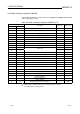
3.4.1 Buffer memory assignment (Q62DA)
This section describes the assignment of the Q62DA buffer memory.
Table 3.6 Buffer memory assignment (Q62DA)
Address
Hexadecimal Decimal
Description
Default
1
Read/write
2
0
H
0 D/A conversion enable/disable 3
H
R/W
1
H
1 CH1 Digital value 0 R/W
2
H
2 CH2 Digital value 0 R/W
3
H
3
to to
A
H
10
System area — —
B
H
11 CH1 Set value code 0 R
C
H
12 CH2 Set value code 0 R
D
H
13
to to
12
H
18
System area — —
13
H
19 Error code 0 R/W
14
H
20 Setting range (CH1 to CH4) 0
H
R
15
H
21 System area — —
16
H
22 Offset/gain setting mode Offset specification 0 R/W
17
H
23 Offset/gain setting mode Gain specification 0 R/W
18
H
24 Offset/gain adjustment value specification 0 R/W
19
H
25
to to
9D
H
157
System area — —
9E
H
158 0R/W
9F
H
159
Mode switching setting
0R/W
A0
H
160
to to
C7
H
199
System area — —
C8
H
200
Pass data classification setting
3
0R/W
C9
H
201 System area — —
CA
H
202
CH1 Industrial shipment settings offset value
3
0R/W
CB
H
203
CH1 Industrial shipment settings gain value
3
0R/W
CC
H
204
CH2 Industrial shipment settings offset value
3
0R/W
CD
H
205
CH2 Industrial shipment settings gain value
3
0R/W
CE
H
206
CH1 User range settings offset value
3
0R/W
CF
H
207
CH1 User range settings gain value
3
0R/W
D0
H
208
CH2 User range settings offset value
3
0R/W
D1
H
209
CH2 User range settings gain value
3
0R/W
1 This is the initial value set after the power is turned on or the PLC CPU is reset.
2 Indicates whether reading and writing to/from a sequence program are enabled.
R : Reading enabled W : Writing enabled
3 Areas used to restore the user range settings offset/gain values when online module change is made.
Refer to chapter 7 for details of online module change.