
User`s manual


App - 4 App - 4
MELSEC-Q
APPENDIX
Appendix 1.4 Precautions for replacing Q62DA/Q64DA/Q68DAV/Q68DAI with
Q62DAN/Q64DAN/Q68DAVN/Q68DAIN
(1) Wiring precautions
To use existing wires of the Q62DA/Q64DA/Q68DAV/Q68DAI, an extra length of
30mm is required for the wiring of an alternative module.
When replacing the module, verify this in the actual system configuration.
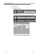
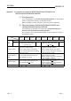
(2) Differences between Q62DA/Q64DA/Q68DAV/Q68DAI and
Q62DAN/Q64DAN/Q68DAVN/Q68DAIN
The following shows the differences between the Q62DA/Q64DA/Q68DAV/
Q68DAI and Q62DAN/Q64DAN/Q68DAVN/Q68DAIN.
These modules can be replaced without taking any specific attention except for
the wiring precautions.
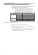
Model
Item
Q62DA Q64DA Q68DAI Q68DAV Q62DAN Q64DAN Q68DAIN Q68DAVN
Voltage No differences
Analog
output
Current
0 to 20 mA DC
(External load resistance value:
see Section 3.1.1)
---
0 to 20 mA DC
(External load resistance value:
0
to 600 )
---
Insulation method
Between the I/O terminal and PLC power
supply: Photo coupler insulation
Between output channels: No insulation
Between external supply power and analog
output: No insulation
Between the I/O terminal and PLC power
supply: Photo coupler insulation
Between output channels: No insulation
Between external supply power and analog
output: Transformer insulation
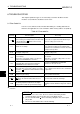
Dielectric withstand
voltage
Between the I/O terminal and PLC power
supply: 500VAC for 1 minute
Between the I/O terminal and PLC power
supply: 500VAC for 1 minute
Between external supply power and analog
output: 500VAC for 1 minute
Insulation resistance
Between the I/O terminal and PLC power
supply: 500VDC 20M or more
Between the I/O terminal and PLC power
supply: 500VDC 20M
or more
Between external supply power and analog
output: 500VDC 20M
or more
External Dimension 98(H) 27.4(W) 90(D) [mm] 98(H) 27.4(W) 112(D) [mm]