
User`s manual


4 - 1 4 - 1
MELSEC-Q
4 SETUP AND PROCEDURES BEFORE OPERATION
4 SETUP AND PROCEDURES BEFORE OPERATION
4.1 Handling Precautions
(1) Do not drop the module case or subject it to heavy impact.
(2) Do not remove the PCB of the module from its case. Doing so may cause the
module to fail.
(3) Be careful not to let foreign particles such as swarf or wire chips enter the module.
They may cause a fire, mechanical failure or malfunction.
(4) The top surface of the module is covered with a protective film to prevent foreign
objects such as wire burrs from entering the module during wiring. Do not remove
this film until the wiring is complete. Before operating the system, be sure to
remove the film to provide adequate heat ventilation.
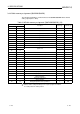
(5) Tighten the terminal screws using torque within the following ranges. Loose
screws may cause short circuits, mechanical failures or malfunctions.
Screw location Clamping torque range
Module mounting screws (M3 screws) 0.36 to 0.48 N
.
m
Terminal block screws (M3 screws) 0.42 to 0.58 N
.
m
Terminal block mounting screws (M3.5 screws) 0.66 to 0.89 N
.
m
FG terminals screws (M3 screws) 0.42 to 0.58 N
.
m
: Q68DAVN, Q68DAIN, Q68DAV, Q68DAI only.
(6) To mount the module on the base unit, fully insert the module fixing latch into the
fixing hole in the base unit and press the module using the hole as a fulcrum.
Improper installation may result in a module malfunction, or may cause the
module to fall off.
4