
Specifications

162
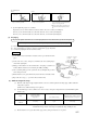
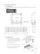
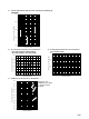
(3) Bottom air inlet grille set
(a) Part number: RTS12
(b) Parts list
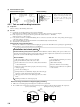
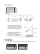
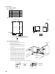
(c) Installation
(d) Installation procedure
1) Mount the duct for the air inlet grille to the indoor unit
using the 10 tapping screws provided. The tapping screws
on the drain pan receiver side are also used for mounting
the duct for the air inlet grille. They must first be removed
and reinstalled after the duct for the air inlet grille is in
place. A guideline for the height is to secure the assembly
so that the lower surface of the duct for the intake grille is
approximately 10 mm above the bottom surface of the
ceiling.
2) Remove the center screw for the air inlet grille and open
the grille as shown in the illustration. Next, insert the air
inlet grille into the duct for the air inlet grille and secure it
with the pan-head screws (the long screws).
3) Use the pan-head screws to make the small adjustments
in height. The height dimension on the installation diagram
allows for adjustment within range of 80 to 100 mm. If
the pan-head screws are completely tightened, the height
will be 80 mm.
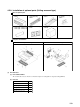
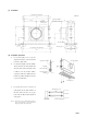
(4) Air outlet unit for ceiling
(a) Part number: RTB12
The air outlet unit uses a flexible duct (ø 150) for blowing the air. Keep the length of the flexible duct within 4 meters for each
unit (straight line parts). (If there is a 90° bend, it should be 1.5 meters.)
(b) Parts list
Name Qty.
1
1
4
Air outlet chamber
Air outlet panel
Pan-head screw
Parts provide with air outlet unit for ceiling
Name Qty.
2
4
4
Suspension bolts (M8)
Flat washers (M8)
Nuts (M8)
Parts procured by customer
Name Qty.
1
1
10
4
Air inlet grille
Duct for air inlet grille
Tapping screw
Pan-head screws
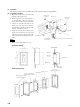
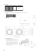
740
Indoor unit
762 (Ceiling opening dimensions)
258 (Ceiling opening dimensions)
278 (Ceiling opening dimensions)
782 (Panel dimensions)
11
2
10
11 11.5455
Indoor unit
Ceiling surface
2
10
2
10
2
10
230
Air outlet side
80 ~ 100
(Drain pan receiver)
Pan-head screw
Air inlet grille
Tapping screw
Duct for air inlet grille
Indoor unit
Unit: mm