Линейка кондиционеров Mitsubishi Heavy на сезон 2002 года. 1. Настенные бытовые сплит-системы. WALL MOUNTED TYPE ROOM AIR CONDITIONER тепло/холод только охлаждение SRK 208 HENF-L SRK 208 СENF-L SRK 258 СENF-L SRK 288 СENF-L SRK 328 СENF-L SRK 408 СENF-L SRK 50 СA SRK 56 СA SRK 288 HENF-L SRK 328 HENF-L2 SRK 408 HENF-L3 SRK 50 HA SRK 56 HA инвертор SRK 25 GZ-L1 SRK 35 GZ-L1 SRK 502 Z-L поддерживаются в наличии на складе в Москве в течении всего 2002 года.
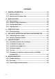
CONTENTS 1.1 GENERAL INFORMATION ........................................................................ 53 1.1.1 Specific features ................................................................................. 53 1.1.2 How to read the model name ............................................................. 53 1.2 SELECTION DATA..................................................................................... 54 1.2.1 Specifications ...........................................................
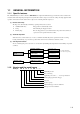
1.1 GENERAL INFORMATION 1.1.1 Specific features The “Mitsubishi Daiya” room air conditioner: SRK series are of split and wall mounted type and the unit consists of indoor unit and outdoor unit with refrigerant precharged in factory. The indoor unit is composed of room air cooling or heating equipment with operation control switch and the outdoor unit is composed of condensing unit with compressor. (1) Remote control flap The flap can be automatically controlled by operating wireless remote control.
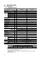
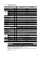
1.2 SELECTION DATA 1.2.1 Specifications Model SRK208HENF-L (Indoor unit) SRC208HENF-L (Outdoor unit) Model SRK208HENF-L Item SRC208HENF-L W 1800/1850 Heating capacity(1) Power source W 2000/2050 1 Phase, 220/240V, 50Hz Cooling input Running current (Cooling) kW A 0.690/0.775 3.4/3.6 Heating input Running current (Heating) kW A 0.620/0.735 3.0/3.4 A 17.3/18.9 2.61/2.
Model SRK288HENF-L (Indoor unit) SRC288HENF-L (Outdoor unit) Model SRK288HENF-L Item SRC288HENF-L W 2500/2500 Heating capacity(1) Power source W 2900/3000 1 Phase, 220/240V, 50Hz Cooling input Running current (Cooling) kW A 0.930/1.005 4.5/4.6 Heating input Running current (Heating) kW A 0.83/0.91 4.0/4.1 A 18.2/19.6 2.69/2.
Model SRK328HENF-L2 (Indoor unit) SRC328HENF-L2 (Outdoor unit) Model SRK328HENF–L2 Item (1) Cooling capacity Heating capacity(1) W W 3000/3000 3800/3800 Cooling input kW 1 Phase, 220/240V, 50Hz 1.39/1.49 Running current (Cooling) Heating input A kW 6.9/6.9 1.19/1.32 Running current (Heating) Inrush current A A 6.1/6.1 33.6/36.
Model SRK408HENF-L3 (Indoor unit) SRC408HENF-L3 (Outdoor unit) Model Item SRK408HENF-L3 SRC408HENF-L3 Cooling capacity W 3500/3500 Heating capacity(1) Power source W 4100/4100 1 Phase, 220/240V, 50Hz Cooling input Running current (Cooling) kW A 1.320/1.405 6.4/6.4 Heating input Running current (Heating) kW A 1.335/1.460 6.5/6.5 A 33.6/36.6 2.65/2.
Model SRK501HENF-L (Indoor unit) SRC501HENF-L (Outdoor unit) Model SRK501HENF–L Item Cooling capacity(1) Heating capacity(1) W W 4500/4500 5700/5800 Cooling input kW 1 Phase, 220/240V, 50Hz 1.78/1.88 Running current (Cooling) Heating input A kW 8.4/8.2 1.76/1.89 Running current (Heating) Inrush current A A 8.5/8.
Model SRK561HENF-L (Indoor unit) SRC561HENF-L (Outdoor unit) Model SRK561HENF–L Item Cooling capacity(1) Heating capacity(1) W W 5000/5000 6200/6300 Cooling input kW 1 Phase, 220/240V, 50Hz 2.08/2.18 Running current (Cooling) Heating input A kW 10.2/9.53 2.02/2.15 Running current (Heating) Inrush current A A 10.5/9.
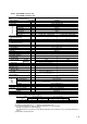
Model SRK50A (Indoor unit) SRC50HA (Outdoor unit) Model SRK50A Item SRC50HA Cooling capacity W 4500 Heating capacity(1) Power source W 5700 1 Phase, 220/230/240V, 50Hz Cooling input Running current (Cooling) kW A 1.79 8.4/8.0/7.7 Heating input Running current (Heating) kW A 1.83 8.5/8.1/7.9 A 39/41/42 2.
Model SRK56A (Indoor unit) SRC56HA (Outdoor unit) Model SRK56A Item SRC56HA W W 5000 6200 Power source Cooling input kW 1 Phase, 220/230/240V, 50Hz 2.08 Running current (Cooling) Heating input A kW 9.7/9.3/8.9 2.10 Running current (Heating) Inrush current A A 9.8/9.4/9.0 44/46/48 Operation data(1) Cooling capacity(1) Heating capacity(1) COP (In cooling) Cooling Noise level Heating 2.
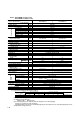
Model SRK208CENF-L (Indoor unit) SRC208CENF-L (Outdoor unit) Model Item Cooling capacity(1) SRK208CENF-L W 1800/1850 Power source 1 Phase, 220/240 V, 50 Hz Cooling input Operation data(1) SRC208CENF-L kW 0.54/0.58 Running current (Cooling) A 2.5/2.6 Inrush current A 11.7/12.8 COP (In cooling) 3.33/3.
Model SRK258CENF-L (Indoor unit) SRC258CENF-L (Outdoor unit) Model Item Cooling capacity (1) SRK258CENF-L W 2200/2250 Power source 1 Phase. 220/240 V, 50 Hz Cooling input Operation data(1) SRC258CENF-L kW 0.66/0.74 Running current (Cooling) A 3.3/3.4 Inrush current A 17.3/18.9 COP (In cooling) 3.33/3.04 Noise level(5) Exterior dimensions Height × Width × Depth dB (A) mm 38/39 41/42 275 × 790 × 174 542 × 795 × 255 Ivory white Polar white 7.
Model SRK288CENF-L (Indoor unit) SRC288CENF-L (Outdoor unit) Model Item Cooling capacity (1) SRK288CENF-L W 2500/2550 Power source 1 Phase, 220/240 V, 50 Hz Cooling input Operation data(1) SRC288CENF-L kW 0.87/0.95 Running current (Cooling) A 4.1/4.2 Inrush current A 18.2/19.6 COP (In cooling) 2.87/2.68 Noise level(5) Exterior dimensions Height × Width × Depth dB (A) mm 38/39 41/42 275 × 790 × 174 542 × 795 × 255 Ivory white Polar white 7.
Model SRK328CENF-L (Indoor unit) SRC328CENF-L (Outdoor unit) Model Item Cooling capacity (1) SRK328CENF-L W 2750/2750 Power source 1 Phase, 220/240 V, 50 Hz Cooling input Operation data(1) SRC328CENF-L kW 0.93/0.99 Running current (Cooling) A 4.3/4.4 Inrush current A 18.2/19.6 COP (In cooling) 2.96/2.
Model SRK408CENF-L (Indoor unit) SRC408CENF-L (Outdoor unit) Model Item Cooling capacity (1) SRK408CENF-L W 3500/3500 Power source 1 Phase, 220/240 V, 50 Hz Cooling input Operation data(1) SRC408CENF-L kW 1.320/1.405 Running current (Cooling) A 6.4/6.4 Inrush current A 33.6/36.6 COP (In cooling) 2.65/2.
Model SRK501CENF-L (Indoor unit) SRC501CENF-L (Outdoor unit) Model Item Cooling capacity(1) SRK501CENF-L SRC501CENF-L W 4500/4500 Power source 1 Phase, 220/240V, 50 Hz Operation data(1) Cooling input kW 1.78/1.88 Running current (Cooling) A 8.4/8.2 Inrush current A 39/42 COP (In cooling) 2.53/2.
Model SRK561CENF-L (Indoor unit) SRC561CENF-L (Outdoor unit) Model Item Cooling capacity (1) SRK561CENF-L SRC561CENF-L W 5000/5000 Power source 1 Phase, 220/240V, 50 Hz Operation data(1) Cooling input kW 2.08/2.18 Running current (Cooling) A 10.2/9.53 Inrush current A 44/48 COP (In cooling) 2.40/2.
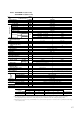
Model SRK50A (Indoor unit) SRC50CA (Outdoor unit) Model SRK50A Item Cooling capacity (1) W 4500 Power source Operation data(1) SRC50CA 1 Phase, 220/230/240V, 50 Hz Cooling input kW 1.79 Running current (Cooling) A 8.4/8.0/7.7 Inrush current A 39/41/42 COP (In cooling) 2.
Model SRK56A (Indoor unit) SRC56CA (Outdoor unit) Model SRK56A Item Cooling capacity (1) W 5000 Power source Operation data(1) SRC56CA 1 Phase, 220/230/240V, 50 Hz Cooling input kW 2.08 Running current (Cooling) A 9.7/9.3/8.7 Inrush current A 44/46/48 COP (In cooling) 2.
1.2 SELECTION DATA 1.2.
Model SRK35GZ-L1 (Indoor unit) SRC35GZ-L1 (Outdoor unit) Model SRK35GZ-L1 Item Refrigerant piping Operation data(1) Cooling capacity(1) Heating capacity(1) Power source Cooling input Running current (Cooling) Heating input Running current (Heating) Inrush current COP (Cooling) Noise level Exterior dimensions Height × Width × Depth Color Net weight Refrigerant equipment Compressor type & Q’ty Motor Starting method Heat exchanger Refrigerant control Refrigerant(4) Refrigerant oil Deice control Air handli
Model SRK502Z-L (Indoor unit) SRC502Z-L (Outdoor unit) Model SRK502Z-L Item Refrigerant piping Operation data(1) Cooling capacity(1) Heating capacity(1) Power source Cooling input Running current (Cooling) Heating input Running current (Heating) Inrush current COP (Cooling) Noise level Exterior dimensions Height × Width × Depth Color Net weight Refrigerant equipment Compressor type & Q’ty Motor Starting method Heat exchanger Refrigerant control Refrigerant(4) Refrigerant oil Deice control Air handling
1.2.2 Range of usage & limitations (1) Inlet air temperature (a) Cooling operation (b) Heating operating Applicable temp. range JIS-Cooling Indoor air temp. ºC D. B. Outdoor air temp. ºC D. B. Applicable temp. range JIS-Heating Indoor air temp. ºC W. B. Note: The chart is the result from the continuous operation under constant air temperature conditions, however, excludes the initial pull-down stage. Outdoor air temp. ºC W. B.
1.2.3 Indoor unit Unit: mm Models SRK 208, 288, 328, 408 -HENF, -CENF, 258CENF A 790 174 3 Room temp. sensor 56 275 Piping hole right (left) 9 Terminal block 760 170 20, 28, 32, 40 models 41 models 187.5 260 61 117 46 9 450 170 49 15 161.5 15 6 ( 67 51 Piping for Gas 20, 28: Ø9.52 32, 40, 41, Ø12.7 390 ) 20.5 60 16 60 36 Remote controller 780 * 62 18 Piping for Liquid (Ø6.
Models SRK50A, 56A
Outdoor unit Model SRC208 H(C) ENF-L Unit: mm Oval holes (4–16x12) 60 MAX 61 50 44 237 265 220 68 14 Drain holes 14 250 120 120 510 750 30 492 Terminal block 65 78 45˚ 80 45˚ 15 Service valve (Liquid) Flare fitting Ø6.35 (1/4˝) Service valve (Gas) Flare fitting Ø9.
Models SRC501H(C)ENF, 561H(C)ENF 510 Unit: mm 170 87 15 850 19 Oval (M10x4) holes for Anchor bolt 30 307 345 15 19 87 25 170 30 70.5 1-28 17 25 Drain pipe 475 615 Service valve (Gas) Ø12.7 (1/2˝) 55 60 290 100 Service valve (Liquid) Ø6.
Models SRC50C(H)A, 56C(H)A 50 328 14 49.6 314 290 43.5 12 12 Drain hole 286.4 476 203.1 510 850 136.9 Elogated hole (2-12X16) Terminal block 640 124 34.6 Service valve (Liquide) Ø6.35 (1/4'') Service valve (Gas) Ø12.7 (1/2'') 15 20˚ 20˚ 100.3 42.
1.2.3 Exterior dimensions (1) Indoor unit Model SRK25GZ-L1 Unit: mm A 178 Room temp. thermistor 750 3 9 250 56 Piping hole right (left) 49 615 75 450 150 236.5 19 15 9 46 150 Terminal block 117 75 16 60 746.9 40 4.5 92 36 36 Remote controller 7.5 62 62 7.5 Piping for Gas (Ø9.52) 370 40 Piping hole (Ø65) 37 Piping for Liquid (Ø6.35) 420 Piping hole (Ø65) VIEW A Model SRK35GZ-L1 Unit: mm A 790 174 3 Room temp.
Model Unit: mm SRK502Z-L Remote controller (2) Outdoor unit Model SRC25GZ-L1 50 Unit: mm 13.5 12 44 274.5 245 42 Drain holes 300 192.5 23 12 372.5 82.5 480 645 82.5 2-Ø12 61.5 Terminal block 33.3 Service valve (Liquid) Flare connecting Ø6.35 (1/4˝) 39.7 540 127.7 100.3 14.4 40˚ 40˚ Service valve (Gas) Flare connecting Ø9.
Model SRC35GZ-L1 50 55 Unit : mm MAX.80 23 14 44 65 93 255 272 58 22 14 Drain holes 265 795 542 539 32 40 413 Terminal block 115 45° 45° 16 12 (Oval holes) for unit fixing 65 2 places 15 44 50 58 14 Model 272 300 14 Drain holes 142.5 510 142.5 33 Service Valve (Liquid) Flare connecting Ø6.35 (1/4¨) Service Valve (Gas) Flare connecting Ø12.
1.2.4 Piping system Model SRK328HENF-L2 Cooling cycle Heating cycle Outdoor unit Indoor unit Service valve (Gas) High pressure switch (63H) (for fan motor control) Flare connecting Piping (Gas) Ø12.7 Heat exchanger Room temperature sensor Heat exchanger sensor Check joint Discharge Compressor Accumulator Heat exchanger 4way valve Suction Piping (Liquid) Ø6.
Models SRK501HENF-L, 561HENF-L Indoor unit Cooling cycle Heating cycle Outdoor unit Service valve (Gas) Flare connecting Piping (Gas) Ø12.7 High pressure switch(63H) (for fan motor control) Check joint 4way valve Room temperature thermistor Heat exchanger thermistor Heat exchanger Discharge Accumulator Deicer thermostat Compressor Muffler Heat exchanger Suction Capillary tube Piping (Liquid) Ø6.
Models SRK501CENF-L, 561CENF-L Indoor unit Outdoor unit Service valve (Gas) Flare connecting Cooling cycle Discharge Piping (Gas) ø12.7 Check joint Room temperature thermistor Heat exchanger Accumulator Heat exchanger Heat exchanger thermistor Suction Compressor Capillary tube Piping (Liquid) ø6.35 Service valve (Liquid) Flare connecting Model SRK408HENF-L Indoor unit Cooling cycle Heating cycle Outdoor unit Service valve (Gas) Flare connecting Piping (Gas) Ø12.
Model SRK408HENF-L3 Indoor unit Cooling cycle Heating cycle Outdoor unit Service valve (Gas) High pressure switch (63H) (for fan motor control) Flare connecting Piping (Gas) Ø12.7 Heat exchanger Room temperature sensor Heat exchanger sensor Check joint Discharge Accumulator Compressor 4way valve Heat exchanger Suction Piping (Liquid) Ø6.
Models SRK288HENF-L, 328HENF-L Cooling cycle Heating cycle Outdoor unit Indoor unit Service valve (Gas) Flare connecting Piping (Gas) Heat exchanger Room temperature sensor Heat exchanger sensor (28:Ø9.52 32:Ø12.7) Check joint Discharge Compressor Accumulator Heat exchanger 4way valve Suction Piping (Liquid) Ø6.
1.2.4 Piping system Models SRK208CENF-L, 258CENF-L, 288CENF-L, 328CENF-L, 408CENF-L Indoor unit Cooling cycle Outdoor unit Flare connecting Service valve (Gas) Piping (Gas) 28 : ø9.52 ( 20, 25, 32, 40 : ø12.7 ) Discharge Room temperature sensor Accumulator Compressor Heat exchanger sensor Suction Capilary tube ø6.
1.2.4 Piping system Model SRK25GZ-L1 Indoor unit Outdoor unit Cooling cycle Heating cycle Flare connecting Piping (Gas) ø9.52 Service valve (Gas) Outdoor air temp. thermistor Check joint 4 way valve Accumulator Room temp. thermistor Discharge temp. thermistor Heat exchanger thermistor Heat exchanger Heat exchanger Compressor Piping (Liquid) ø6.
Model 1-40 SRK502Z-L
1.3 ELECTRICAL DATA 1.3.1 Electrical wiring Models SRK50CA, 56CA Power source 1 Phase 220/230/240V 50Hz Indoor unit Y/GN BL BR OR 4 RD 3 WH 2 BK 1 Y/GN 52C-4 G 52C Outdoor unit 52C-3 S 20S BL 4 BL F (250V 100mA) 3 WH 2 BK 1 RD 23D BK 52C PC 5 4 3 F 250V 3.
Models SRK501CENF-L, 561CENF-L Outdoor unit Indoor unit Power source 1 Phase 220/240V 50Hz LB BR G 1 BL Y WH BK RD F 250V 3.
Model SRK208CENF-L Indoor unit Outdoor unit Power source 1 Phase 220/240V 50Hz Wireless R-Amp Display Printed circuit board Color symbol BK Black BL Blue BR Brown RD Red OR Orange WH Y/GN White Yellow/Green Meaning of marks Symbol Parts name Symbol CC Capacitor for CM LM Parts name Louver motor CFI Capacitor for FMI Th1, 2 Thermistor CFO Capacitor for FMO Tr Transformer CM Compressor motor ZNR Fuse 51C Motor protector for CM FMI Fan motor (Indoor unit) 52C Magnetic c
Models SRK258CENF-L, 288CENF-L, 328CENF-L, 408CENF-L Indoor unit Outdoor unit Power source 1 Phase 220/240V 50Hz Wireless R-Amp Display Printed circuit board Color symbol BK Black BL Blue BR Brown RD Red OR Orange WH Y/GN White Yellow/Green Meaning of marks Symbol Parts name Symbol Parts name CC Capacitor for CM LM CFI Capacitor for FMI Th1, 2 Thermistor CFO Capacitor for FMO Tr Transformer CM Louver motor Compressor motor ZNR Varistor Fuse 51C Motor protector for CM
Model SRK208HENF-L Indoor unit Outdoor unit Power source 1Phase 220/240V 50Hz Wireless R-Amp Display Printed circuit board Color symbol BK Black BL Blue BR Brown RD Red OR Orange WH White Y/GN Yellow/Green Meaning of marks Symbol Parts name Cc Capacitor for CM Symbol Th1, 2 Parts name Thermistor CFI Capacitor for FMI Tr CFO Capacitor for FMO ZNR Varistor CM Compressor motor 20S 4 way valve, coil Fuse 51C Motor protector for CM Fan motor (Indoor unit) 52C Magnetic c
Models SRK288HENF-L, 328HENF-L, 408HENF-L Indoor unit Outdoor unit Power source 1Phase 220/240V 50Hz Wireless R-Amp Display Printed circuit board Color symbol BK Black BL Blue BR Brown RD Red OR Orange WH White Y/GN Yellow/Green Meaning of marks Symbol Parts name Cc Capacitor for CM Symbol Th1, 2 Parts name Thermistor CFI Capacitor for FMI Tr CFO Capacitor for FMO ZNR Varistor CM Compressor motor 20S 4 way valve, coil Fuse 51C Motor protector for CM Fan motor (Indoor
Models SRK328HENF-L2, 408HENF-L2 Indoor unit Outdoor unit Y/GN Power source 1 Phase 220/240V 50Hz BL BK RD BK 63H 52C OR WH Printed circuit board 20S WH Display 7 BK 52X5 8 CFo Wireless R-Amp WH CNE CND ZNR BK OR FMo 3 1 C 23DH 2 RD BK RD Th2 2 2 52X6 6 S 7 52X6 RD BK BK 52X4 Th1 CFI CNM LM PC CNG BK OR CNU 1 5 3 CNW FMI BR WH RD 4 52C F 250V 3.
Models SRK501HENF-L, 561HENF-L Indoor unit RD 63H RD 23D 52C 52XA WH 23 DH OR 20S 51C CM 52XA RD 52XB Cc BL OR CF0 BK OR WH Display BK OR FM0 Wireless R-Amp BL RD RD ) ZNR BK 52XB 6 CNM LM 2 BK ( TH2 CNH FMI 52X1 52X1 F 250V 3.
Models SRK50HA, 56HA Indoor unit Outdoor unit RD 63H RD 23D 52C 52XA 20S RD BK OR 51C CM 52XA RD CF0 52XB Cc BL Back up sw BK RD WH WH Display CNE ZNR BL WH FM0 Wireless R-Amp 23 DH 52XB BK ) CNM LM TH2 BK BK BK ( WH 52X1 52X1 F 250V 3.
Model SRK408HENF-L3 Indoor unit Outdoor unit Y/GN Power source 1 Phase 220/240V 50Hz BL BK RD BK 63H 52C OR WH Printed circuit board 20S 7 WH Display 8 Color symbol BK Black BL Blue BR Brown RD Red OR Orange WH Y/GN White Yellow/Green Meaning of marks Symbol Parts name Cc Capacitor for CM Symbol Th1,2 Parts name Thermistor CFI Capacitor for FMI Tr CFO Capacitor for FMo ZNR Varistor CM Compressor motor 20S 4 way valve, coil Fuse 51C Motor protector for CM FMI Fan
White Violet Yellow/Green WH V Y/GN Yellow Y Red Light blue LB Gray Brown BR RD Blue BL GY Black BK Color symbol SM Y WH RD BK BR FMI WH LB CNM CNU CNW Y/GN Y/GN Power source 1 phase 220/240V 50Hz CFI Display Wireless R-Amp CNE CNC Tr CNB F1 (250V 3.
1-52 White Violet Yellow/Green WH V Y/GN Yellow Y Red Light blue LB Gray Brown BR RD Blue BL GY Black BK Color symbol SM Y WH RD BK BR FMI WH LB CNM CNU CNW Y/GN Y/GN Power source 1 phase 220/240V 50Hz CFI Display CNE CNC Tr Wireless R-Amp CND CNB F1 (250V3.
Light blue White Yellow/Green Y/GN Red RD LB Yellow Y CNE ( Display ) CNH 52C J Th3 CNF Th2 Th1 CNG Printed circuit board ZNR S Back up switch 52C-3 F 250V 3.
1.4 OUTLINE OF OPERATION CONTROL BY MICROCOMPUTER 1.4.1 Table for operation control Refering page Functions High efficiency, low input rotary compressor Wireless remote control Dry ON TIMER 3 Hot system [Heat Pump type only] (in heating operation) Automatic fan control Micro computer control Comfortability, Economical efficiency, Operational simplicity OFF TIMER HOT START HOT SPURT HOT KEEP Micro computer (MC) controlled timely defrosting operation (in heating) M. C.
(1) Remote controller S 50, 56 models HI POWER operation indicator Indicators during HI POWER operation. FAN SPEED indicator ECONOMY operation indicator Indicators the ¡ for the fan speed which has been set. Indicators during ECONOMY operation. Operation switch over indicator Indicators the ¡ for the operation which has been set. ON-TIMER • OFF-TIMER indicator AIR FLOW indicator Indicates selected flap mode.
(4) Operation control function by remote control switch Remote control switch S Models SRK 208, 258, 288, 328, 408 models OPERATION MOOD select button Each time the button is pushed, the • indicator is switch over in turn. CONT AUTO HI MED LO FAN SPEED button Each time the button is pushed, the • indicator is switched over in turn. ON/OFF button Press for starting operation, press again for stopping. FAN SPEED ON OFF TIMER ON / OFF AIRFLOW button MODE This button changes the flap mode.
(3) Back-up Switch When the remote controller batteries become weak, or if the remote controller is lost or malfunctioning, this switch may be used to turn the unit on and off. (a) Operation Push the switch once to place the unit in the automatic mode. Push it once more to turn the unit off. (b) Details of operation The unit will go into the automatic mode in which it automatically determines, from room temperature (as detected by sensor), whether to go into the cooling, thermal dry or heating modes.
(c) When switching to automatic operation during “Heating” “Cooling” “Dry” or when restarting with in 30 minutes (40 : 1 hour) after stopping with automatic operation mode, the former operating mode is selected. (In this case, 20 seconds Lo operation of indoor fan is not performed). When the previous mode is in “FAN”, operation mode is to be set by the above mentioned chart. (d) Established temperature (operate by the established temperature button on remote controller).
1.2.5 Selection chart Correct the cooling and heating capacity in accordance with the conditions as follows. The net cooling and heating capacity can be obtained in the following way. Net capacity = Capacity shown on specification ✕ Correction factors as follows. (1) Coefficient of cooling and heating capacity in relation to temperatures Coefficient of cooling & Heating capacity in relation to temperature 1.3 1.2 Cooling 1.1 1.0 Heating 0.9 0.8 0.7 0.6 Outdoor air D.B. temperature °C D.B.
Additional refrigerant charge When refrigerant piping exceeds 7(40 : 7.5) m conduct additional refrigerant charge after refrigerant sweeping. S 50, 56 models 7m over 15m : Additional charge amount per meter = 20g/m S 40 model Max.
(7) Standard operation data (a) Heat pump type (220/240V) Model Item High pressure (kgf/cm2G) Low pressure (kgf/cm2G) Temp. difference between suction air and discharge air (˚C) Running current (A) SRK208HENF-L SRK288HENF-L SRK328HENF-L SRK408HENF-L Cooling – – – – Heating 15 ~ 17 17 ~ 19 17 ~ 19 18 ~ 20 Cooling 4.5 ~ 5.5 4~5 4.5 ~ 5.5 4~5 Heating – – – – Cooling 14 ~ 16 11 ~ 15 12 ~ 16 12 ~ 16 Heating 16 ~ 18 18 ~ 22 18 ~ 22 18 ~ 22 Cooling 3.4/3.6 4.5/4.6 6.9/6.9 6.
(220/230/240V) Model Item High pressure MPa(kgf/cm2) Low pressure MPa(kgf/cm2) Temp. difference between suction air and discharge air (˚C) Running current (A) SRK50HA Cooling SRK56HA – – Heating 1.86 ~ 2.06 (19~21) 1.86 ~ 2.06 (19~21) Cooling 0.39 ~ 0.49 (4 ~ 5) 0.34 ~0.44 (3.5 ~ 4.5) Heating – – Cooling 12 ~ 16 12 ~ 16 Heating 19 ~ 23 21 ~ 25 Cooling 8.4/8.0/7.7 9.7/9.3/8.9 Heating 8.5/8.1/7.9 9.8/9.4/9.
(220/240V) Model Item High pressure MPa(kgf/cm2) Low pressure MPa(kgf/cm2) Temp. difference between suction air and discharge air (˚C) Running current (A) SRK501HENF-L Cooling SRK561HENF-L – – Heating 1.67~1.86 (17 ~ 19) 1.76 ~ 1.96 (18 ~ 20) Cooling 0.39 ~ 0.49 (4 ~ 5) 0.34 ~0.44 (3.5 ~ 4.5) Heating – – Cooling 12 ~ 16 13 ~ 18 Heating 19 ~ 23 21 ~ 25 Cooling 8.4/8.2 10.2/9.53 Heating 8.5/8.3 10.5/9.
1.6 MAINTENANCE DATA 1.6.1 Trouble shooting (1) Trouble shooting to be performed prior to exchanging PCB, (Printed circuit board) [Common to all models] All the models described in this chapter are controlled by a microcomputer. When providing maintenance service to customers it is necessary to understand the function controlled by a micro computer thoroughly, so as not to mistakenly identify correct operations as mis-operations.
(2) Indication of Self Diagnosis (Indoor unit) Connect of Defect TIMER lamp is lights continuously. RUN lamp is lights continuously. Place of defect RUN lamp is flashing. (1 Time flash.) Abnormality of heat exchanger thermistor. ¡ Disconnection of heat exchanger thermistor. RUN lamp is flashing. (2 Time flash.) Abnormality of room temperature thermistor. ¡ Disconnection of room temperature thermistor. RUN lamp is flashing. (6 Time flash.) Abnormality of indoor fan motor.
Anormality of thermistor Disconnection of thermistor and defective connection of connector Chart for thermistor temperature resistance characteristics Is connection to connector good? No Repair connector. (Disconnection) Is thermistor resistance value normal? No Resistance value Yes Replace thermistor. Yes (kΩ) Replace PCB. (Short circuit) Temperature (°C) (4) Trouble Diagnostic Procedures Unit malfunctions or does not stop. Indoor lamp of indoor unit does not illuminate. Remove receptacle.
(5) Trouble shooting chart for the room temperature thermistor (Th1), heat exchanger thermistor (Th2) and defrost thermostat (23DH) Unit Thermistor Function Operation Room temperature thermistor (1) (Th1) except for “continuous” thermal setting. Short circuit Cooling Indoor unit Heating Cooling will not operate ¡ FMI : continuous operation ¡ CM,FMo: stopped Heating will not operate (CM, FMo, FMI all stopped) Continuous heating operation. ¡ Cannot be turned ON/OFF by thermostat ¡ When FMI is on.
1.6.3 Power supply remote operation When the remote part on indoor unit PCB is modified, the air conditioner is turned ON-OFF by power supply ON-OFF operation without using remote control switch. After the power supply remote operation, the operation contents can be modified by the remote controller.