
Installation Instructions

-
14
-
'13 • SRK-T-144
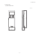
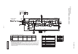
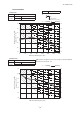
(2) Outdoor units
Models SRC20ZMX-S, 25ZMX-S, 35ZMX-S
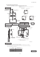
RWC000Z272
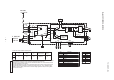
Description
Item
Connector
Electric expansion valve(coil)
EEV
Fan motorFMo
ReactorL
Terminal blockTB1
Compressor motorCM
Solenoid valve for 4 way valve20S
Heat exchanger sensor(outdoor unit)
TH2
Outdoor air temp.sensorTH3
TH4 Discharge pipe temp.sensor
CN20S
CNTH
CNEEV
CNFAN
Color
RD
Mark
OrangeOR
Yellow/Green
Y/G
Black
BK
YellowY
WhiteWH
Red
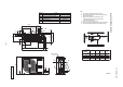
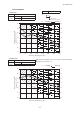
Power cable, indoor-outdoor connecting wires
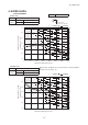
・The specifications shown in the above table are for units without heaters. For units with heaters, refer
to the installation instructions or the construction instructions of the indoor unit.
・Switchgear of Circuit breaker capacity which is calculated from MAX. over current should be chosen
along the regulations in each country.
・The cable specifications are based on the assumption that a metal or plastic conduit is used with no
more than three cables contained in a conduit and a voltage drop is 2%. For an installation falling
outside of these conditions, please follow the internal cabling regulations. Adapt it to the regulation
in effect in each country.
20
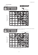
Model
MAX running current
Power cable size
(mm )
2
(A)
Power cable length
(m)
indoor-outdoor
wire size x number
Earth wire size
25
2.0
32
35
1.5mm x 3
2
8
1.5
(mm )
2
3
1
2
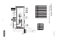
TO INDOOR UNIT
POWER WIRES
SIGNAL WIRE
N
POWER SOURCE
TB1
TERMINAL
BLOCK
L
N
1
3
2
(BK)
R.IN
250V 15A
(BK)
(WH)
(Y/G)
(Y/G)
(Y/G)
(RD)
C-2
G1
G2
S.IN
FILTER
NOISE
F1
250V 3.15A
T1
T2
(OR)
(Y)
L
20S
2
2 2 2
CN20S CNTH CNEEV
TH2 TH3 TH4
M
EEV
CIRCUIT
POWER
SWITCHING
F4
250V 10A
CIRCUIT
PAM
250V 20A
F2
PCB ASSY PWB1
TRANSISTOR
POWER
(BK)
(WH)
(RD)
N
P
W
V
U
W
V
U
M
3~
CM
F3 250V 1A
CNFAN
FMo
M
∼220ー240V 50Hz