5. UTILIZATION OF EXISTING PIPING
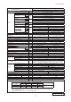
Check whether an existing pipe system is reusable or not by using the following flow chart. START Are an outdoor unit and an indoor unit connected to the existing pipe system to reuse? YES NO NO Are the existing units our products? YES YES Does the existing pipe system to reuse satisfy all of the following? (1) The pipe length is 30m or less. (2) The pipe size conforms to the table of pipe size restrictions.'13 • SRK-T-144 9. OUTLINE OF OPERATION CONTROL BY MICROCOMPUTER (1) Operation control function by wireless remote control Operation section Transmission section OPERATION MODE select button ON/OFF (luminous) button Each time the button is pressed, the mode changes. Press to start operation, press again to stop. TEMPERATURE button FAN SPEED button This button sets the room temperature. Each time the button is pressed, the fan speed changes.
'13 • SRK-T-144 (2) Unit ON/OFF button When the wireless remote control batteries become weak, or if the wireless remote control is lost or malfunctioning, this button may be used to turn the unit on and off. (a) Operation Push the button once to place the unit in the automatic mode. Push it once more to turn the unit off.
'13 • SRK-T-144 (5) Selection of the annual cooling function (a) The annual cooling function can be enabled or disabled by means of the jumper wire (J172) on the indoor unit PCB and the dip switch (SW2-4) on the interface kit (option) PCB.
'13 • SRK-T-144 (8) Flap and louver control Control the flap and louver by AIRFLOW (LEFT/RIGHT) button on the wireless remote control. (UP/DOWN) and (a) Flap Each time when you press the AIRFLOW (UP/DOWN) button the mode changes as follows. (Flap stopped) (Swing) Angle of Flap from Horizontal Remote control display (b) COOL , DRY, FAN Approx. 5° Approx. 20° Approx. 35° Approx. 45° Approx. 60° HEAT Approx. 20° Approx. 35° Approx. 45° Approx. 60° Approx.
'13 • SRK-T-144 (9) 3D auto operation Control the flap and louver by 3D AUTO button on the wireless remote control. Air flow selection and air flow direction are automatically controlled, allowing the entire indoor to efficiently conditioned. (a) During Cooling and Heating (Including auto cooling and heating) (i) Air flow selection is determined according to indoor temperature and setting temperature. Operation mode Cooling Heating Air flow selection AUTO Indoor temp. – Setting temp. >5°C Indoor temp.
'13 • SRK-T-144 (10) Timer operation (a) Comfortable timer setting (ON timer) If the timer is set at ON when the operation select switch is set at the cooling or heating, or the cooling or heating in auto mode operation is selected, the comfortable timer starts and determines the starting time of next operation based on the initial value of 15 minutes and the relationship between the indoor temperature at the setting time (temperature of room temperature sensor) and the setting temperature.
'13 • SRK-T-144 Airflow range Airflow range (Left End Installation) Airflow range (Center Installation) (Right End Installation) (iv) Press the ON/OFF button. The air-conditioner's installation location is set. Press within 60 seconds of setting the installation location (while the installation location setting display illuminates).
'13 • SRK-T-144 4) The difference between the outdoor air sensor temperature and the outdoor heat exchanger sensor temperature ¡ The outdoor air temperature ≧ 0ºC (model SRK50, 60 : ≧ -2ºC) : 7ºC or higher ¡ - 15ºC ≦ The outdoor air temperature < 0ºC (model SRK50, 60 : < -2ºC) : 4/15 × The outdoor air temperature + 7ºC or higher ¡ The outdoor air temperature < -15ºC : -5ºC or higher Models SRK20~35 Models SRK50, 60 0 Outdoor heat exchanger temperature (℃) Outdoor heat exchanger temperature (℃) 0 -5
'13 • SRK-T-144 (b) Detail of control in each mode (Pattern) (i) Fuzzy operation During the fuzzy operation, the air flow and the compressor speed are controlled by calculating the difference between the indoor temperature setting correction temperature and the return air temperature.
'13 • SRK-T-144 (b) The unit checks the temperature every hour after the start of operation and, if the result of check is not same as the previous operation mode, changes the operation mode. (c) When the unit is started again within one hour after the stop of automatic operation or when the automatic operation is selected during heating, cooling or dehumidifying operation, the unit is operated in the previous operation mode. (d) Setting temperature can be adjusted within the following range.
'13 • SRK-T-144 (b) Frost prevention control (During cooling or dehumidifying) (i) Operating conditions 1) Indoor heat exchanger temperature (Th2) is lower than 5ºC. 2) 5 minutes after reaching the compressor command speed except 0 rps. (ii) Detail of anti-frost operation compressor command speed 5°C or lower 2.
'13 • SRK-T-144 (d) Cooling high pressure control (i) Purpose: Prevents anomalous high pressure operation during cooling. (ii) Detector: Outdoor heat exchanger sensor (TH1) (iii) Detail of operation: Model SRK50, 60 Model SRK20~35 A Outdoor heat exchanger temperature (ºC) B 53 58 C Outdoor heat exchanger temperature (ºC) 63 A B C TH2 > = 32ºC 53 58 63 TH2 < 32ºC 51 53 56 TH2 : Outdoor air temperature (Example) Fuzzy 6 (8) rps(1) After lapse of 30 (20) sec.
'13 • SRK-T-144 (f) Heating high pressure control (i) Purpose: Prevents anomalous high pressure operation during heating. (ii) Detector: Indoor heat exchanger sensor (Th2) (iii) Detail of operation: (Example) Fuzzy 4rps(1) After lapse of 20 (10) sec. or over(3) 8rps(2) 4rps After lapse of 20 (10) sec. or over(3) 8rps (1) (2) lower limit (3) After lapse of 20 (10) sec.
calculation exceeds the upper limit, the upper limit value is maintained. b) The lower limit of compressor command speed is set to 40 rps and even if the calculated result becomes lower than that after fuzzy calculation, the speed is kept to 40 rps. However, when the thermo OFF, the speed is reduced to '13 • SRK-T-144 0 prs. c) rps. d) Protective control Normal operation 21 22 Outdoor air temperature(°C) .
'13 • SRK-T-144 • Models SRK50, 60 (i) Operating conditions: When the outdoor air temperature (TH2) is lower than 4ºC or higher continues for 30 seconds while the compressor command speed is other than 0 rps. (ii) The lower limit compressor command speed is change as shown in the figure below. Detail of operation: Lower limit 45 rps Lower limit 35 rps Normal operation -8 -6 4 6 Outdoor air temperature (°C) (iii) Reset conditions: (i) When either of the following condition is satisfied.
'13 • SRK-T-144 (k) Current cut (i) Purpose: Inverter is protected from overcurrent. (ii) Detail of operation: Output current from the inverter is monitored with a shunt resistor and, if the current exceeds the setting value, the compressor is stopped immediately. Operation starts again after a delay time of 3 minutes. (I) Outdoor unit failure This is a function for determining when there is trouble with the outdoor unit during air conditioning.
'13 • SRK-T-144 (ii) Heating 1) Operating conditions: When the outdoor air temperature (TH2) is 4ºC or lower continues for 30 seconds while the compressor command speed is other than 0 rps. 2) Detail of operation: The outdoor fan is stepped up by 2 speed step at each 20 seconds. (Upper limit 8th speed) 3) Reset conditions: When either of the following conditions is satisfied (r) a) The outdoor air temperature (TH2) is 6ºC or higher. b) The compressor command speed is 0 rps.
'09•SRK-DB-087D '13 • SRK-T-144 Reference 10.
'09•SRK-DB-087D '13 • SRK-T-144 (4) Troubleshooting procedure (If the air conditioner runs) NO YES 65 NO 66-72. YES YES NO 66-72.
'09•SRK-DB-087D '13 • SRK-T-144 (5) Self-diagnosis table Indoor unit display panel Outdoor Wired remote Description control PCB control RUN TIMER of trouble Red LED display light light (3) (2) Cause Display (flashing) condition 1-time flash ON — — Heat exchanger sensor 1 error • Broken heat exchanger sensor 1 wire, poor connector connection • Indoor PCB is faulty When a heat exchanger sensor 1 wire disconnection is detected while operation is stopped.
'09•SRK-DB-087D '13 • SRK-T-144 (6) Service mode (Trouble mode access function) (a) Explanation of terms Term Explanation Service mode The service mode is the mode where service data are displayed by flashing of the display lights when the operations in item (b) below are performed with the indoor controller. Service data These are the contents of error displays and protective stops which occurred in the past in the air conditioner system.
'09•SRK-DB-087D '13 • SRK-T-144 2-time flash. 4-time flash mode wireless mode (i) Self-diagnosis data wireless mode mode Wireless remote control setting Operation mode Fan speed mode Contents of output data wireless Temperature setting Indicates the number of occasions previous to the present the error display data are from.
'09•SRK-DB-087D '13 • SRK-T-144 (Example) Wireless remote control setting Operation mode Cooling Displayed data Fan speed Temperature mode setting MED 21ºC Displays the reason for the stop (error code) the previous time an error was displayed. 22ºC Displays the reason for the stop (error code) 2 times previous when an error was displayed. 23ºC Displays the reason for the stop (error code) 3 times previous when an error was displayed.
'09•SRK-DB-087D '13 • SRK-T-144 (c) Error code, stop code table Number of flashes when in service mode Stop coad RUN or TIMER light Error coad light (10's digit) (1's digit) 3-time flash 4-time flash 5-time flash 6-time flash 8-time flash Cause Occurrence conditions Error Auto display recovery 0 Normal 5-time flash 05 Can not receive signals for 35 Power supply is faulty. When 35 seconds passes without Power supply cables and signal lines are improperly wired.
'09•SRK-DB-087D '13 • SRK-T-144 s 4-time flash 2-time flash.
'09•SRK-DB-087D '13 • SRK-T-144 (e) Temperatare information (i) Room temperature sensor, indoor heat exchanger sensor, outdoor air temperature sensor, outdoor heat exchanger sensor temperature.
'09•SRK-DB-087D '13 • SRK-T-144 (ii) Discharge pipe sensor temperature. Units: °C TIMER light (1’s digit) RUN light (10’s digit) 0 1 2 3 4 5 6 7 8 9 3 -60 -62 -64 2 -40 -42 -44 -46 -48 -50 -52 -54 -56 -58 1 -20 -22 -24 -26 -28 -30 -32 -34 -36 -38 -2 -4 -6 -8 -10 -12 -14 -16 -18 Buzzer sound Yes (sounds for 0.
'09•SRK-DB-087D '13 • SRK-T-144 Service data record form Wireless r Operation mode Fan speed mode Wireless r Wireless r Wireless r Wireless r Wireless r wireless - 73 - 67)
'09•SRK-DB-087D '13 • SRK-T-144 (7) Inspection procedures corresponding to detail of trouble Sensor error Broken sensor wire, connector poor connection Sensor temperature characteristics (Room temp., indoor heat exchanger temp., outdoor heat exchanger temp., outdoor air temp.
'09•SRK-DB-087D '13 • SRK-T-144 Current cut Compressor lock, Compressor wiring short circuit, Compressor output is open phase, Outdoor PCB is faulty, Service valve is closed, EEV is faulty, Compressor faulty. 84 * * SRC20-35 : 1.703Ω (U-V, V-W, U-W) or more at 20ºC SRC50, 60 : 0.
'09•SRK-DB-087D '13 • SRK-T-144 Over heat of compressor Gas shortage, defective discharge pipe sensor 74) Error of signal transmission Wiring error including power cable, defective indoor/ outdoor PCB ② ③ ② ③ ① ② - 76 -
'09•SRK-DB-087D '13 • SRK-T-144 Trouble of outdoor unit Insufficient refregerant amount, Faulty power transistor, Broken compressor wire Service valve close, Defective EEV, Defective outdoor PCB AC AC AC AC AC AC (1) (2) ◆ (1) (3) 84 Notes (1) (2) Check coil wire resistance, see page 75.
'13 • SRK-T-144 Rotor lock Defective compressor, defective outdoor PCB See page 75.
'13 • SRK-T-144 (8) Phenomenon observed after shortcircuit, wire breakage on sensor (a) Indoor unit Phenomenon Operation mode Sensor Room temperature sensor Cooling Heat exchanger sensor Cooling Shortcircuit Disconnected wire Heating Freezing cycle system protection trips and stops the compressor. Heating (1) Humidity sensor Cooling Heating Note (1) SRK 50, 60 only.
Replace indoor PCB. blocks ② and ③ oscillating between DC 0 and 20V? YES '13 • SRK-T-144 Indoor electrical components are normal.
Operation SW ON Measure in this section '13 • SRK-T-144 (10) How to make sure of wireless remote control wireless wireless wireless wireless wireless wireless Simplified check methd of wireless remote control It is normal if the signal transmission section of the wireless remote control emits a whitish light at each transmission on the monitor of digital camera or camera of mobile phone.
'13 • SRK-T-144 (12) Outdoor unit inspection points Models SRC20ZMX-S, 25ZMX-S, 35ZMX-S ◆Check point of outdoor unit CAUTION- HIGH VOLTAGE ◆Power source and serial signal inspection L to N : AC 220/230/240V 1 to 2/N : AC 220/230/240V 2/N to 3 : Normal if the voltage oscillates between DC 0 and approx. 20V High voltage is produced in the control box. Don't touch electrical parts in the control box for 5 minutes after the unit is stopped.
'13 • SRK-T-144 Models SRC50ZMX-S, 60ZMX-S ◆Check point of outdoor unit CAUTION- HIGH VOLTAGE ◆Power source and serial signal inspection L to N : AC 220/230/240V 1 to 2/N : AC 220/230/240V 2/N to 3 : Normal if the voltage oscillates between DC 0 and approx. 20V High voltage is produced in the control box. Don't touch electrical parts in the control box for 5 minutes after the unit is stopped.
'09•SRK-DB-087D '13 • SRK-T-144 (a) Inspection of electronic expansion valve (i) (ii) 3 1 2 DC Red Blue 4 Orange White 5 Yellow 6 (iii) (iv) • Inspection of electronic expansion valve as a separate unit Measuring point Resistance when normal (b) Outdoor unit fan motor check procedure (i) 1) 2) 3) ② FM0 Measuring point White Yellow Blae ⑥ ⑤ ④ ③ ② ① ⑥ ⑤ ④ ③ ② ① Red Black ⑥−④ CNFAN ③−④ ②−④ Outdoor PCB DC several (4~7V) GND (−) DC308~336V DC15V (ii) Fan motor resistance
'13 • SRK-T-144 11. OPTION PARTS PJA012D730 manual (1) WiredInstallation remote control (RC-E5) for wired remote controller Read together with indoor unit's installation manual. WARNING Fasten the wiring to the terminal securely and hold the cable securely so as not to apply unexpected stress on the terminal. Loose connection or hold will cause abnormal heat generation or fire. Make sure the power supply is turned off when electric wiring work.
'13 • SRK-T-144 mote controller o apply unexpected stress on the Connect the remote control cord to the terminal block. Connect the terminal of remote control (X,Y) with the terminal of indoor unit (X,Y). (X and Y are no polarity) Wiring route is as shown in the right diagram depending on the pulling out direction.
'13 • SRK-T-144 PJA012D730 eath Sheath Upper er case Upper case Board Lower The range of temperature setting Wiring In case of pulling out from upper center ecommended) to 0.5mm2. The peeling-off length of sheath rol cord, and tighten with as not to slack. (on-site configuration) nge the wire size outside of sary at the wire connecting r one group of indoor units.) ntents ote control te control Upper Board Lower o "Master" for shipment.
'13 • SRK-T-144 The functional setting The initial function setting for typical using is performed automatically by the indoor unit connected, when remote control and indoor unit are connected. As long as they are used in a typical manner, there wiil be no need to change the initial settings. If you would like to change the initial setting marked “ ”, set your desired setting as for the selected item. The procedure of functional setting is shown as the following diagram.
'13 • SRK-T-144 Note 1: The initial setting marked “ Item Function No. Remote control function02 Remote control function06 Remote control function07 Remote control function13 ” is decided by connected indoor and outdoor unit, and is automatically defined as following table. Default Model "Auto-RUN" mode selectable indoor unit.
'13 • SRK-T-144 PJA012D730 utomatically defined as following table. Operation message Function description: setting description: How to set function e indoor unit. N" mode step of air flow setting air flow setting y swing louver cally swing louver air flow setting air flow setting (SET) (MODE) 1. Stop air-conditioner and press buttons at the same time for over three seconds, and the "FUNCTION SET " will be displayed. , Fixing button 2. Press (SET) button. 3.
'13 • SRK-T-144 (2) Interface kit (SC-BIKN-E) RKZ012A088B Accessories included in package Safety precautions Be sure to check all the accessories included in package. ●All the cautionary items mentioned below are important safety related items to be taken into consideration, so be sure to observe them at all times. No. Part name Quantity ① Indoor unit's connection cable (cable length: 1.
'13 • SRK-T-144 Installation of the interface ・Install the interface within the range of the connection cable length from the indoor unit. (approximately 1.8m) Wiring inlet ・Be sure not to extend the connection cable on site. If the connection cable is extended, malfunction may occur. ・Fix the interface on the wall, pillar or the like. DO NOT install the interface and wired remote control at the following places.
'13 • SRK-T-144 Functions of CNT connector It is available to operate the air conditioning unit and to monitor the operation status with the external control unit (remote display) by sending the input/output signal through CNT connector on the indoor control PCB. ①Connect a external remote control unit (procured locally) to CNT terminal. ②In case of the pulse input, switch OFF the DIP switch SW2-1 on the interface PCB.
'13 • SRK-T-144 Connection of wired remote control Regarding the connection of wired remote control, refer to the instruction manual of wired remote control. ①Switch ON the DIP switch SW2-2 (Factory setting : ON) on the interface PCB. DIP suitch (SW2-2) Caution:Wireless remote control attached to the indoor unit can be used in parallel, after connecting the wired remote control. However, some of functions other than the basic functions such as RUN/STOP, Temperature Setting, etc.
'13 • SRK-T-144 (3) Super link E board (SC-ADNA-E) F CAUTION WARING - 95 -
'13 • SRK-T-144 - 96 -
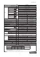
'13 • SRK-T-144 12. TECHNICAL INFORMATION Model SRK20ZMX-S Information to identify the model(s) to which the information relates to: Indoor unit model name SRK20ZMX-S Outdoor unit model name SRC20ZMX-S ( 11/ ) A If function includes heating: Indicate the heating season the information relates to. Indicated values should relate to one heating season at a time. Include at least the heating season 'Average'.
'13 • SRK-T-144 Model SRK25ZMX-S Information to identify the model(s) to which the information relates to: Indoor unit model name SRK25ZMX-S Outdoor unit model name SRC25ZMX-S A ( 12/ ) If function includes heating: Indicate the heating season the information relates to. Indicated values should relate to one heating season at a time. Include at least the heating season 'Average'.
'13 • SRK-T-144 Model SRK35ZMX-S Information to identify the model(s) to which the information relates to: Indoor unit model name SRK35ZMX-S Outdoor unit model name SRC35ZMX-S A ( 13/ ) If function includes heating: Indicate the heating season the information relates to. Indicated values should relate to one heating season at a time. Include at least the heating season 'Average'.
'13 • SRK-T-144 Model SRK50ZMX-S Information to identify the model(s) to which the information relates to: Indoor unit model name SRK50ZMX-S Outdoor unit model name SRC50ZMX-S ( 4/ ) If function includes heating: Indicate the heating season the information relates to. Indicated values should relate to one heating season at a time. Include at least the heating season 'Average'.
'13 • SRK-T-144 Model SRK60ZMX-S Information to identify the model(s) to which the information relates to: Indoor unit model name SRK60ZMX-S Outdoor unit model name SRC60ZMX-S ( 5/ ) If function includes heating: Indicate the heating season the information relates to. Indicated values should relate to one heating season at a time. Include at least the heating season 'Average'.
INVERTER WALL MOUNTED TYPE RESIDENTIAL AIR-CONDITIONERS Air-Conditioning & Refrigeration Systems 16-5, Konan 2-chome, Minato-ku, Tokyo, 108-8215 Japan http://www.mhi.co.jp Because of our policy of continuous improvement, we reserve the right to make changes in all specifications without notice. C Copyright MITSUBISHI HEAVY INDUSTRIES, LTD.