
Indoor Installation Manual


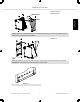


Table Of Contents
- SVZ-KP12,18, 24, 30, 36NA
- Table of Contents
- SVZ-KP12,18, 24, 30, 36NA
- 1. Dimensions
- 2. Inspect shipment
- 3. Safety precautions
- 4. Indoor unit accessories
- 5. Selecting an installation site
- 6. Combining indoor units with outdoor units
- 7. Installing the unit
- 8. Side Return
- 9. Duct connection
- 10. Mount positions
- 11. Air filter
- 12. Refrigerant piping work
- 13. Drain connections
- 14. Electrical wiring
- 15. Test run
- SVZ-KP12,18, 24, 30, 36NA
- 1. Dimensions
- 2. Inspection du matériel livré
- 3. Mesures de sécurité
- 4. Accessoires de l’appareil intérieur
- 5. Sélection de l’emplacement d’installation
- 6. Combinaison des appareils intérieurs et extérieurs
- 7. Installation de l’appareil
- 8. Retour latéral
- 9. Raccordement des conduits
- 10. Positions de montage
- 11. Filtre à air
- 12. Travaux de tuyauterie de frigorigène
- 13. Raccordements de vidange
- 14. Câblage électrique
- 15. Essai de fonctionnement
- 15.1. Avant l’essai de fonctionnement
- 15.2. Essai de fonctionnement
- 15.3. Autotest
- 15.4. FONCTION D’AUTOREDÉMARRAGE

SCALE 0.125
SCALE 0.125
1ST
2ND
SCALE 0.125
D
E
F
Step. 2 Remove the panel marked “BLOWER”.
① 1st
② 2nd
Step. 3a Remove the screws securing the (3) panels to the COIL panel shown in the image above.
Remove the “1st” panel and “2nd” panel marked “COIL”.
SVZ-KP12,18, 24, 30, 36NA
Specifications are subject to change without notice. 23 © 2022 Mitsubishi Electric US, Inc.
ENGLISH