SPLIT-TYPE, HEAT PUMP AIR CONDITIONERS December 2018 No. OCH699 HFC utilized R410A SERVICE MANUAL R410A Outdoor unit [Model Name] SUZ-KA09NA2 SUZ-KA09NAH2 SUZ-KA12NA2 SUZ-KA12NAH2 SUZ-KA15NA2 SUZ-KA15NAH2 [Service Ref.] SUZ-KA09NA2.MX SUZ-KA09NAH2.MX SUZ-KA12NA2.MX SUZ-KA12NAH2.MX SUZ-KA15NA2.MX SUZ-KA15NAH2.MX Air inlet (back and side) Piping Air outlet Drain hose Drain outlet SUZ-KA09NA(H)2.MX Note: This service manual describes service data of the outdoor units only. CONTENTS 1.
1 COMBINATION OF INDOOR AND OUTDOOR UNITS Outdoor unit Heat pump type Indoor unit Service Manual No. Heat pump without electric heater Service Ref. 2 SUZKA12 NA(H)2.MX KA15 NA(H)2.MX OCH699 SLZ-KF09/12/15NA.TH SEZ-KD09/12/15NA4R1.TH HWE08020 PEAD-A09/12/15AA7.MX HWE1608A SVZ-KP12NA.MX MLZ-KP09/12NA-U1 KA09 NA(H)2.MX — — OBH802 — PART NAMES AND FUNCTIONS SUZ-KA09NA(H)2.MX SUZ-KA12NA(H)2.MX SUZ-KA15NA(H)2.
SPECIFICATION Outdoor unit model Power supply Max. fuse size (time delay) Min. circuit ampacity Fan motor Model Compressor Refrigerant control Sound level*1 Defrost method Dimensions V , phase , Hz A A F.L.A R.L.A L.R.A Refrigeration oil oz(L)/ (Model) Cooling Heating W D H dB(A) dB(A) SUZ-KA09NA(H)2 SUZ-KA15NA(H)2 KNB073FRVMC 6.2 7.7 SUZ-KA12NA(H)2 208/230 , 1 , 60 15 9 0.50 SNB092FQAMT 6.6 8.2 9.1(0.27)/(FV50S) 11.8(0.35)/(FV50S) 11.8(0.
OUTLINES AND DIMENSIONS Unit: inch(mm) SUZ-KA09NA(H)2.MX SUZ-KA12NA(H)2.MX SUZ-KA15NA(H)2.MX *1 4 in. (100 mm) or more when front and sides of the unit are clear clear *1 REQUIRED SPACE ) mm 00 re 1 ( o n. 4 i or m 4 in .( or 100 m mo re m) (KA09/12/15NA) (KA09/12/15NAH) ) mm 00 . (2 ore *2 n i 8 rm o 14 in.
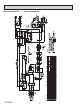
WIRING DIAGRAM SUZ-KA09NA2.MX OCH699 SUZ-KA12NA2.
SUZ-KA09NAH2.MX OCH699 SUZ-KA12NAH2.
SUZ-KA15NA2.
SUZ-KA15NAH2.
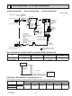
6 REFRIGERANT SYSTEM DIAGRAM SUZ-KA09NA(H)2.MX SUZ-KA12NA(H)2.MX SUZ-KA15NA(H)2.MX Unit: Inch (mm) Refrigerant pipe ø3/8 (ø9.52) (KA09/12) ø1/2 (ø12.7) (KA15) (with heat insulator) 4-way valve Muffler Stop valve (with service port) Flared connection Service port Capillary tube O.D. 0.118 × I.D. 0.079 × 9-7/16 (ø3.0 × ø2.0 × 240) (KA09) Capillary tube O.D. 0.157 × I.D. 0.094 × 9-7/16 (ø4.0 × ø2.
7 DATA Outdoor Indoor unit unit Refrigerant circuit Electrical circuit Total Outdoor Indoor unit unit Refrigerant circuit Electrical circuit Total STANDARD OPERATION DATA Representative matching Item Unit Capacity BTU/h SHF Input kW Indoor unit Power supply (V, phase, Hz) Input kW Current A Outdoor unit Power supply (V, phase, Hz) Input kW Current A Condensing pressure PSIG Suction pressure PSIG Discharge temperature °F Condensing temperature °F Suction temperature °F Ref.
Total Electrical circuit Refrigerant circuit Outdoor Indoor unit unit Total Electrical circuit Refrigerant circuit Outdoor Indoor unit unit Representative matching Item Unit Capacity BTU/h SHF Input kW Indoor unit Power supply (V, phase, Hz) Input kW Current A Outdoor unit Power supply (V, phase, Hz) Input kW Current A Condensing pressure PSIG Suction pressure PSIG Discharge temperature °F Condensing temperature °F Suction temperature °F Ref.
8 ACTUATOR CONTROL 8-1. OUTDOOR FAN MOTOR CONTROL The fan motor turns ON/OFF, interlocking with the compressor. [ON] The fan motor turns ON 5 seconds before the compressor starts up. [OFF] The fan motor turns OFF 15 seconds after the compressor has stopped running. ON 5 seconds 15 seconds Compressor OFF ON Outdoor fan motor OFF 8-2. R.V. COIL CONTROL Heating. . . . . . . . . . . . . . . . . . ON Cooling . . . . . . . . . . . . . . . . . . OFF Dry . . . . . . . . . . . . . . . . . . . . .
9 SERVICE FUNCTION 9-1. CHANGE IN DEFROST SETTING Changing defrost finish temperature To change the defrost finish temperature, cut/solder the JS wire of the outdoor inverter P.C. board. (Refer to "10-6. TEST POINT DIAGRAM AND VOLTAGE".) Jumper JS Defrost finish temperature SUZ-KA09/12/15 Soldered (Initial setting) 41°F (5°C) None (Cut) 50°F (10°C) 9-2.
10-2. TROUBLE SHOOTING CHECK TABLE SUZ-KA09NA(H)2.MX SUZ-KA12NA(H)2.MX LED check No. Symptoms LED check code Abnormal point/ Condition indication No. Symptoms indication code Abnormal point/ Condition 1 1 Outdoor unit 1-time flash UP Outdoor power sysOutdoor 1-time blink Outdoor power system does not optem every uniterate. does not every2.5 seconds UP operate. 2.5 seconds U3 Outdoor thermistors U3 Outdoor thermistors SUZ-KA15NA(H)2.
10-3. HOW TO PROCEED "SELF-DIAGNOSIS" As this air conditioner has a function to memorize all the failures that had occurred, the latest failure detail can be recalled by following the procedure below. Use this function when the check code is not displayed with wired remote controller or the remote controller at use is wireless type. 10-3-1. Self-diagnosis 1 Select "Service" from the Main menu, and press the button.
10-3-2. Self-diagnosis When a malfunction occurs to air conditioner, both indoor unit and outdoor unit will stop and operation lamp blinks to inform unusual stop.
• Refer to the following tables for details on the check codes. [Output pattern A] Beeper sounds OPERATION INDICATOR lamp blink pattern Beep Beep Beep Beep Off Beep 1st 2 nd 3 rd nth On On On On Beep Beep 1st Off On 2 nd · · · Repeated On 0.5 sec. Approx. 2.5 sec. 0.5 sec. 0.5 sec. Self-check Approx. 2.5 sec. 0.5 sec. 0.5 sec. 0.5 sec.
10-4. TROUBLE CRITERION OF MAIN PARTS SUZ-KA09NA(H)2.MX SUZ-KA12NA(H)2.MX SUZ-KA15NA(H)2.MX Part name Check method and criterion Defrost thermistor (RT61) Measure the resistance with a tester. Fin temperature thermistor (RT64) Refer to “Inverter P.C. board” in "10-6. TEST POINT DIAGRAM AND VOLTAGE”, for the chart of thermistor.
10-5. TROUBLESHOOTING FLOW A How to check inverter/compressor Disconnect the connector (CN61) between compressor and the intelligent power module (IPM). See 10-5. Check the voltage between terminals. Are the voltages balanced? Yes No Replace the inverter P.C. board. See 10-5. Check the compressor. “Check of open phase”. “Check of compressor”.
D Check of compressor winding ● Disconnect the connector between the compressor and intelligent power module, and measure the resistance between the compressor terminals. Measure the resistance between the lead wires at 3 points. BK - WH BK - RD WH - RD Refer to "10-4. TROUBLE CRITERION OF MAIN PARTS". 0[Ω]·················· Abnormal [short] Infinite [Ω]········· Abnormal [open] NOTE: Be sure to zero the ohmmeter before measurement.
G Check of outdoor thermistors Disconnect the connector of thermistor in the outdoor P.C. board (see below table), and measure the resistance of thermistor. Is the resistance of thermistor normal? (Refer to "10-6.TEST POINT DIAGRAM AND VOLTAGE".) Yes No Replace the thermistor except RT64. When RT64 is abnormal, replace the inverter P.C. board. Reconnect the connector of thermistor. Turn ON the power supply and press EMERGENCY OPERATION switch.
I Check of outdoor fan motor Check the connection between the connector CN931 and CN932. Disconnect the connectors CN931 and CN932 from the inverter P.C. board. Is the resistance between each terminal of outdoor fan motor normal? (Refer to 10-4.) No Yes Disconnect CN932 from the inverter P.C. board, and turn on the power supply. Rotate the outdoor fan motor manually and measure the voltage of CN931.
J Check of power supply Disconnect the connector between compressor and intelligent power module. Turn ON power supply and press the TEST button twice on the indoor unit or remote controller. Does the POWER lamp on remote controller light up? Rectify indoor/outdoor connecting wire. No Yes Is there bus-bar voltage 260-370 VDC between DB61 (+) and DB61 (–) on the inverter P.C. board? (Refer to "106.TEST POINT DIAGRAM AND VOLTAGE.") No Yes Check the electric parts in main circuit.
L Check of inverter P.C. board Check the outdoor fan motor. (Refer to "10-5. . Check of outdoor fan motor".) Is the fuse (F901) blown on the inverter P.C. board? Yes No Check the connection of the connectors (CN931, CN932) of the outdoor fan motor. If the connection is poor, make it correct. Operate the outdoor unit by starting EMERGENCY OPERATION. Check the LED indication on the inverter P.C. board.
M How to check miswiring and serial signal error Turn OFF the power supply. Is there rated voltage in the power supply? Yes Check the power supply. No Turn ON the power supply. Is there rated voltage between the outdoor terminal block S1 and S2? Yes No Check the wiring. Press TEST button twice.
N Check the defrost heater SUZ-KA09/12/15NAH2 Check the following points before checking electric continuity. 1. Does the resistance of ambient temperature thermistor have the characteristics? Refer to 10-6.1. 2. Is the resistance of defrost heater normal? Refer to 10-4. 3. Is the heater protector closed? 4.
P Electromagnetic noise enters into TV sets or radios Is the unit grounded? Yes Is the distance between the antennas and the indoor unit within 9.91 ft., or is the distance between the antennas and the outdoor unit within 9.91 ft.? Ground the unit. No Yes Extend the distance between the antennas and the indoor unit, and/or the antennas and the outdoor unit. Yes Extend the distance between the TV sets and/or radios and the indoor unit, or the TV sets or radios and the outdoor unit.
10-6. TEST POINT DIAGRAM AND VOLTAGE Inverter P.C. board SUZ-KA09NA(H)2.MX SUZ-KA12NA(H)2.MX SUZ-KA15NA(H)2.MX Smoothing capacitor (C63) DB61 260 - 370 VDC (-) (+) Back side of unit Smoothing capacitor (C62) R.V.coil Heater connector (CN722) (CN721) Smoothing (SUZ-KA09/ 208/230 VAC capacitor (C61) 12/15NAH2) Fuse (F701) T3.15AL250V Fuse (F801) T3.15AL250V 208/230 VAC Fuse (F901) T3.
11 FUNCTION SETTING 11-1. UNIT FUNCTION SETTING BY THE REMOTE CONTROLLER Each function can be set according to necessity using the remote controller. The setting of function for each unit can only be done by the remote controller. Select function available from the table 1.
Function selections (1) Functions available when setting the unit number to 00 (Select 00 referring to 4 setting the indoor unit number.) Mode No.11-1-1. Selecting functions using the wired remote controller Maintenance password is required 1 Select "Service" from the Main menu, and press the button. *At the main display, the menu button and select "Service" to make the maintenance setting. Main Main menu Maintenance Initial setting Service Main display: Cursor 2 When the Service menu is selected, a window will appear asking for the pass- F1 F2 F3 Service menu word.
1 Select "Service" from the Main menu, and press the Service menu button. Select "Function setting" with the F1 or F2 button, and press the Test run Input maintenance info. Function setting Check Self check button. Main menu: Cursor F1 2 Set the indoor unit refrigerant addresses and unit numbers with the F1 through F4 buttons, and then press the setting. button to confirm the current
12 DISASSEMBLY INSTRUCTIONS <"Terminal with locking mechanism" Detaching points> The terminal which has the locking mechanism can be detached as shown below. There are two types (refer to (1) and (2)) of the terminal with locking mechanism. The terminal without locking mechanism can be detached by pulling it out. Check the shape of the terminal before detaching. (1) Slide the sleeve and check if there is a locking lever or not. (2) The terminal with this connector has the locking mechanism.
OPERATING PROCEDURE Photo 4 PHOTOS/FIGURES Photo 5 Screws of the conduit cover 2. Removing the inverter assembly, inverter P.C. board (1) Remove the cabinet and panels. (Refer to 1.) (2) Disconnect the lead wire to the reactor and the following connectors: CN721 (R.V.
OPERATING PROCEDURE PHOTOS/FIGURES 4. Removing the discharge temperature thermistor, defrost thermistor, outdoor heat exchanger temperature thermistor and ambient temperature thermistor Photo 8 Screw of the R.V. coil (1) Remove the cabinet and panels. (Refer to 1.) (2) Disconnect the lead wire to the reactor and the following connectors:
OCH699 35
HEAD OFFICE: TOKYO BUILDING., 2-7-3, MARUNOUCHI, CHIYODA-KU, TOKYO100-8310, JAPAN Copyright 2018 MITSUBISHI ELECTRIC CORPORATION Published : Dec. 2018 No.OCH699 Made in Japan Specifications are subject to change without notice.