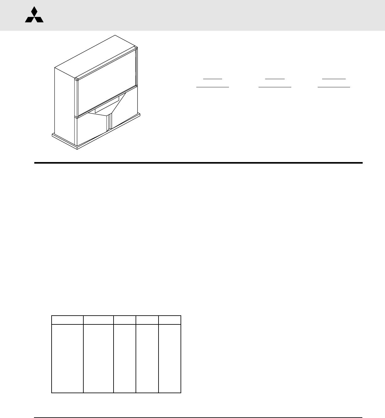
Ser vice Manual 2002 MITSUBISHI ELECTRIC PROJECTION TELEVISION V20A / V20C / V20C+ CHASSIS V20A MODELS V20C MODELS V20C+ MODELS VS-50111 VS-60111 WS-48311 WS-55311 WS-65311 WS-55411 WS-65411 WS-73411 WS-55411 WS-65411 WS-73411 CAUTION: Before servicing this chassis, it is important that the service person read the "SAFETY PRECAUTIONS" and "PRODUCT SAFETY NOTICE" contained in this manual.
MODELS: VS-50111 / VS-60111 / WS-48311 / WS-55311 / WS-55411 / WS-65311 / WS-65411 / WS-73411 CONTENTS INTRODUCTION ................................................................................................................................ 5 PRODUCT SAFETY NOTICE ............................................................................................................. 5 SAFETY PRECAUTIONS ...............................................................................................................
MODELS: VS-50111 / VS-60111 / WS-48311 / WS-55311 / WS-55411 / WS-65311 / WS-65411 / WS-73411 Dynamic Focus Preset ........................................................................................................ 36 Lens Focus .......................................................................................................................... 36 Electrostatic Focus & Alignment Magnet Adjustment .......................................................... 37 On Screen Display Character Position ...
MODELS: VS-50111 / VS-60111 / WS-48311 / WS-55311 / WS-55411 / WS-65311 / WS-65411 / WS-73411 INTRODUCTION This service manual provides service instructions for the PTV Models listed below. Service personnel should read this manual thoroughly before servicing these chassis. V20A Chassis VS-50111 VS-60111 V20C Chassis WS-48311 WS-55311 WS-65311 V20C+ Chassis WS-55411 WS-65411 WS-73411 This service manual includes: 1. Assembly and disassembly instructions for the front and rear cabinet components. 2.
MODELS: VS-50111 / VS-60111 / WS-48311 / WS-55311 / WS-55411 / WS-65311 / WS-65411 / WS-73411 SAFETY PRECAUTIONS NOTICE: WARNING: 1. 2. 3. Observe all cautions and safety related notes located inside the receiver cabinet and on the receiver chassis. Operation of this receiver outside the cabinet or with the cover removed presents a shock hazard from the receiver's power supplies.
MODELS: VS-50111 / VS-60111 / WS-48311 / WS-55311 / WS-55411 / WS-65311 / WS-65411 / WS-73411 CABINET DISASSEMBLY (FRONT VIEW) WS-48311 *Refer to PARTS LIST for Part Numbers Front Cabinet Disassembly 1. Remove the Speaker Grille by pulling forward. 2. Remove the Board-Front by removing screws "a". 3. Remove the Screen Assembly by removing screws "b". Disconnect all cable harnesses between the Screen Assembly and the PCB-Signal. 4. Lift the Screen Assembly and pull up and away from the cabinet as shown.
MODELS: VS-50111 / VS-60111 / WS-48311 / WS-55311 / WS-55411 / WS-65311 / WS-65411 / WS-73411 CABINET DISASSEMBLY (REAR VIEW) WS-48311 Rear Cabinet Disassembly 1. 2. 3. 4. Remove the Back Board by removing screws "a", “b” and “c”. Remove the Back Cover by removing screws "e". Remove 4 screws "d" securing the Light Box Assembly. Be certain that all cables and connectors between the Light Box Assembly and external items are disconnected (e.g. speaker plugs). 5.
MODELS: VS-50111 / VS-60111 / WS-48311 / WS-55311 / WS-55411 / WS-65311 / WS-65411 / WS-73411 CABINET DISASSEMBLY (FRONT VIEW) VS-50111 VS-60111 WS-55311 WS-65311 Front Cabinet Disassembly 1. Remove the Speaker Grille by pulling forward. 2. Remove the Front-Board by removing screws "a". 3. Remove the Screen Assembly by removing screws "b". Disconnect all cable harnesses between the Screen Assembly and the PCB-Signal. 4. Lift the Screen Assembly and pull up and away from the cabinet as shown.
MODELS: VS-50111 / VS-60111 / WS-48311 / WS-55311 / WS-55411 / WS-65311 / WS-65411 / WS-73411 CABINET DISASSEMBLY (FRONT VIEW) WS-55411 WS-65411 WS-73411 Front Cabinet Disassembly 1. 2, 3. 4. Remove the Speaker Grille by pulling forward. Remove the Control Panel by removing screws “a”. Remove the Board-Front by removing screws "b". Remove the Screen Assembly by removing screws "c". Disconnect all cable harnesses between the Screen Assembly and the PCB-Signal. 4.
MODELS: VS-50111 / VS-60111 / WS-48311 / WS-55311 / WS-55411 / WS-65311 / WS-65411 / WS-73411 CABINET DISASSEMBLY (REAR VIEW) VS-50111 VS-60111 WS-55311 WS-55411 WS-65311 WS-65411 WS-73411 Rear Cabinet Disassembly 1. 2. 3. 4. 5. Remove the Back Board by removing screws "a". Remove the Board Slide by removing screws “b”. Remove the two Board Shelves by removing screws “c”. Remove 4 screws "d" securing the Light Box Assembly.
MODELS: VS-50111 / VS-60111 / WS-48311 / WS-55311 / WS-55411 / WS-65311 / WS-65411 / WS-73411 SERVICING THE LENTICULAR SCREEN AND FRESNEL LENS VS-50111 VS-60111 WS-55311 WS-65311 1. Removal of the Lenticular Screen and Fresnel Lens CAUTION: Wear gloves when handling the Lenticular Screen and the Fresnel Lens. This prevents cuts and finger prints. Do not place the Fresnel Lens in the sun. This may cause fire and heat related injuries. 1.
MODELS: VS-50111 / VS-60111 / WS-48311 / WS-55311 / WS-55411 / WS-65311 / WS-65411 / WS-73411 SERVICING THE LENTICULAR SCREEN AND FRESNEL LENS WS-55411 CAUTION: WS-65411 WS-73411 Wear gloves when handling the Lenticular Screen and Fresnel Lens. This prevents cuts and finger prints. Do not place Fresnel Lens in the sun. This may cause fire and heat related injuries. 1b. Lenticular Screen and Fresnel Lens Removal 1. Remove the screen assembly as shown in the Cabinet Disassembly procedure. 2.
MODELS: VS-50111 / VS-60111 / WS-48311 / WS-55311 / WS-55411 / WS-65311 / WS-65411 / WS-73411 SERVICING THE LENTICULAR SCREEN AND FRESNEL LENS WS-48311 CAUTION: Wear gloves when handling the Lenticular Screen and Fresnel Lens. This prevents cuts and finger prints. Do not place Fresnel Lens in the sun. This may cause fire and heat related injuries. 1c. Lenticular Screen and Fresnel Lens Removal 1. Remove the screen assembly as shown in the Cabinet Disassembly procedure. 2.
MODELS: VS-50111 / VS-60111 / WS-48311 / WS-55311 / WS-55411 / WS-65311 / WS-65411 / WS-73411 2. Installation of the Lenticular Screen and Fresnel Lens Note: Store the Lenticular Screen and Fresnel Lens in a cool dry place. High humidity may deform the Lenticular Screen and Fresnel Lens. 1. Apply double coated tape (Part # LENS-TAPE) along the top front edge of the Fresnel Lens as shown in Figure 2-2. Refer to Table A and Table B for proper tape length. 2.
MODELS: VS-50111 / VS-60111 / WS-48311 / WS-55311 / WS-55411 / WS-65311 / WS-65411 / WS-73411 CABINET SEPARATION PROCEDURE (WS-65311 / WS-65411 / WS-73411) Models WS-65311, WS-65411 and WS-73411 cabinets are assembled in two pieces. These two pieces may be separated to allow easier delivery and setup. WS-65311 Cabinet Separation Precedure 1. Remove the Screen Assembly and disconnect all cable harnesses between the Frame Assembly and the PCB-SIGNAL, refer to Cabinet Front Disassembly. 2.
MODELS: VS-50111 / VS-60111 / WS-48311 / WS-55311 / WS-55411 / WS-65311 / WS-65411 / WS-73411 SERVICING THE DIAMONDSHIELD™ 1. DiamondShield™ Removal Procedure The location of the DiamondShieldTM molding clips may vary between models, top and bottom, or sides. Use the appropriate disassembly procedure given below. Note: Wear gloves when handling the DiamondShield™ to prevent finger prints. Side Molding Clips Top & Bottom Molding Clips 1.
MODELS: VS-50111 / VS-60111 / WS-48311 / WS-55311 / WS-55411 / WS-65311 / WS-65411 / WS-73411 SERVICING PCBs Chassis Removal and PCB Locations Chassis Removal 1) Remove screw “a” from the Main Chassis. 2) Raise the two chassis locks on the inner sides of the Lightbox Assembly and slide the chassis towards the rear.
MODELS: VS-50111 / VS-60111 / WS-48311 / WS-55311 / WS-55411 / WS-65311 / WS-65411 / WS-73411 ANODE LEAD REMOVAL CAUTION: To prevent damage, the following procedure must be used when removing an Anode Lead from the Flyback Transformer. 1) Push the Anode Lead down. 2) While holding the lead down rotate the lead 90º counter clockwise. 3) Carefully remove the Anode Lead from the Flyback Transformer. CRT REPLACEMENT 1.
MODELS: VS-50111 / VS-60111 / WS-48311 / WS-55311 / WS-55411 / WS-65311 / WS-65411 / WS-73411 Note: The 4 spring-loaded screws shown in Fig 5-2 and labeled as "DO NOT REMOVE", should not be loosened under any circumstance. Doing so will break the seal between the CRT and the CRT-Spacer, causing leakage of the CRT Coolant. Figure 5-2 2.
MODELS: VS-50111 / VS-60111 / WS-48311 / WS-55311 / WS-55411 / WS-65311 / WS-65411 / WS-73411 1. Carefully position the replacement CRT and fasten in place using 4 screws "d". [Figure 5-5] 2. Install the Deflection Yoke on the CRT neck. [Figure 5-6] 3. Install the Lens that was removed in steps 5 and 6 of Removal Of The CRT. [ Figures 5-1 and 5-2 ] a) Position the Lens so that the Label faces the direction shown in Figure 5-7 b) Install the mounting screws. [Figure 5-1] 4. Install the PCB-CRT. 5.
MODELS: VS-50111 / VS-60111 / WS-48311 / WS-55311 / WS-55411 / WS-65311 / WS-65411 / WS-73411 ELECTRICAL ADJUSTMENTS Note: Perform only the adjustments required. Do not attempt an alignment if proper equipment is not available. 1. Test Equipment • • • • • • Oscilloscope (Unless otherwise specified, use 10:1 probes) Signal Generator (both SD and HD capable) Frequency Counter Direct Current Voltmeter Direct Current Power Supply Multiplex Audio Signal Generator Direct Current Ampere Meter 2. Test Signal A.
MODELS: VS-50111 / VS-60111 / WS-48311 / WS-55311 / WS-55411 / WS-65311 / WS-65411 / WS-73411 3. Initial Setup A. Option Menu Setup Follow the steps below for the initial set-up: 1. Select the "MENU" display by pressing the "MENU" button once. 2. Press the number buttons "2", "2", "7", "0" in sequence to select the "OPTION MENU" display. 3. Press the "ADJUST" button to select "INITIAL." 4. Press "ENTER." NOTE: At this time channel 3 is automatically selected.
MODELS: VS-50111 / VS-60111 / WS-48311 / WS-55311 / WS-55411 / WS-65311 / WS-65411 / WS-73411 Items in the table below are set to following after Initalization. AV Memory Initial Settings A/V Memory Ant-A Ant-B Max Mid Mid Mid Mid High Stnd. Video Contrast Brightness Sharpness Color Tint Color Temp. Video Noise Image type TV VSM On Sharpness Bass Mid Mid Treble Mid Balance Off Surround Stereo Listen To Off Level Sound Max Mid Mid Mid Mid High Stnd. Video NTSC 1/2/3 Max Mid Mid Mid Mid High Stnd.
MODELS: VS-50111 / VS-60111 / WS-48311 / WS-55311 / WS-55411 / WS-65311 / WS-65411 / WS-73411 5. Circuit Adjustment Mode Except for the following, all adjustment items must be performed using the remote hand unit. • Lens Focus • Electrostatic Focus FUNCTION CHASSIS Video Chr A. Activating the Circuit Adjustment Mode 1. Press the "MENU" button on a remote hand unit. MODE 2. Press the number buttons "2", "2", "5", "7" in sequence. ITEM# The screen will change to the Adjustment Mode.
MODELS: VS-50111 / VS-60111 / WS-48311 / WS-55311 / WS-55411 / WS-65311 / WS-65411 / WS-73411 D. Saving Adjustment Data Press “ENTER” to save adjustment data in memory. The character display turns red for approximately one second in this step. Note: If the circuit adjustment mode is terminated without pressing “ENTER”, changes in adjustment data are not saved. E. Terminating the Circuit Adjustment Mode Press the “MENU” button on the remote hand unit twice to terminate the adjustment mode.
MODELS: VS-50111 / VS-60111 / WS-48311 / WS-55311 / WS-55411 / WS-65311 / WS-65411 / WS-73411 1. 2. Use the VIDEO button to select an item. Use the ADJUST buttons to change data. Note: When Item “1 HVOL” is selected the screen goes black except for the data display. This occurs since a black screen is required when making the HV Regulation adjustment. E. COARSE CONV (Press 5) There are four Sub Functions in the Coarse mode, COARSE GREEN, COARSE RED, COARSE BLUE and DF. • COARSE GREEN ....
MODELS: VS-50111 / VS-60111 / WS-48311 / WS-55311 / WS-55411 / WS-65311 / WS-65411 / WS-73411 Cursor Coordinates Specific intersections in the Crosshatch are assigned vertical and horizontal coordinates. These are shown in the preceeding diagram. The Cursor can only be moved to those positions that have coordinates assigned. If the Cursor is at coordinates outside the screen area, the Cursor will not be visible. Use the ADJUST buttons to move the Cursor to an intersection on the screen.
MODELS: VS-50111 / VS-60111 / WS-48311 / WS-55311 / WS-55411 / WS-65311 / WS-65411 / WS-73411 Deflection Jungle Menu-2-2-5-7 48" 50"/60" 55" 65" 73" Item# Abbrev. Description Range HD NTSC HD NTSC HD NTSC HD NTSC HD NTSC 1 HWID Width 0~63 31 31 31 31 29 31 29 31 31 31 2 HKEY Horiz. Keystone 0~63 31 31 31 31 25 24 31 24 31 31 3 EWPT Top EW-PCC 0~63 31 31 31 31 31 31 31 31 31 31 7 VHGT Height 0~63 28 40 30 37 17 15 44 40 28 40 8 VLIN Vert. Linearity 0~15 5 5 5 5 5 5 7 7 5 5 9 VSCN Vert. S Corr.
MODELS: VS-50111 / VS-60111 / WS-48311 / WS-55311 / WS-55411 / WS-65311 / WS-65411 / WS-73411 COARSE CONV GREEN (MENU-2-2-5-9-5) # Abbrev. Description WS-48311 VS-50111 WS-55311 WS-55411 VS-60111 WS-65311 WS-65411 WS-73411 SD HD SD HD SD HD SD HD SD HD SD HD SD HD SD HD 1 HSTA Horiz. Position 0 0 0 0 0 0 0 0 0 0 0 0 0 0 0 0 2 VSTA Vert.
MODELS: VS-50111 / VS-60111 / WS-48311 / WS-55311 / WS-55411 / WS-65311 / WS-65411 / WS-73411 Adjustment Test Point Location Test Points DT pin 3 - HV Adjust DT pin 6 - Ground DT pin 7 - 12 Volts DT pin 8 - ACL JA pin 17 - Main Picture (Y) JA pin 21 - Main Color (Pr) JB pin 1 - Sub Picture (Y) JB pin 3 - Sub Picture (Cr) TP6(R, G or B) - CRT Cathode Page 31
MODELS: VS-50111 / VS-60111 / WS-48311 / WS-55311 / WS-55411 / WS-65311 / WS-65411 / WS-73411 [HV Circuit] Purpose: To set the CRT Anode voltage. 1. HV Regulation Symptom: Dark Picture Measuring Instrument DC Voltmeter Note: This adjustment must be rechecked following Adjustment 9 CRT Cutoff. Test Point DT connector pins 3 & 6 Ext. Trigger ------ Measuring Range ------- Input Signal Video Signal Monoscope Input Terminal Video Input 1. Supply a video monoscope signal. 2.
MODELS: VS-50111 / VS-60111 / WS-48311 / WS-55311 / WS-55411 / WS-65311 / WS-65411 / WS-73411 [Video Circuit] Purpose: 3. Main/Sub Color Level Symptom: Main and sub pictures colors differ. Measuring Instrument Oscilloscope Test Point JA pin 21 JB pin 3 ------ Ext. Trigger Measuring Range ------ Input Signal Color Bars Input Terminal Video To match the sub picture color to that of the main picture. 1. 2. 3. 4. 5. 6. Supply an NTSC signal to an External Video Input.
MODELS: VS-50111 / VS-60111 / WS-48311 / WS-55311 / WS-55411 / WS-65311 / WS-65411 / WS-73411 [CRT Circuit] Purpose: To set the CRTs white level in the NTSC mode. 5. White Balance (NTSC) Symptom: Monochrome has a color tint. Measuring Instrument DC Voltmeter Note: Use the “FORMAT” button to activate the Expand mode (full screen). Test Point ------ Ext. Trigger ------ Measuring Range ------ Input Signal NTSC White Raster Input Terminal RF or Video 1. 2. 3. 4. 5. 6. 7. 8. 9. 10. 11.
MODELS: VS-50111 / VS-60111 / WS-48311 / WS-55311 / WS-55411 / WS-65311 / WS-65411 / WS-73411 [Video Circuit] Purpose: To set the black level of the picture. 7. Black Level Symptom: Excess or insufficient brightness. Measuring Instrument ----- Test Point ----- Ext. Trigger ------ Measuring Range ------ Input Signal Monoscope Input Terminal 1. Supply a Monoscope signal to a Video Input. 2. Activate the Adjust Mode, Video Chroma Function. 3.
MODELS: VS-50111 / VS-60111 / WS-48311 / WS-55311 / WS-55411 / WS-65311 / WS-65411 / WS-73411 [Focus Circuit] Purpose: 9. Dynamic Focus Preset Symptom: Poor focus at the edges of the screen. Measuring Instrument ----- Test Point ----- Ext. Trigger ------ Measuring Range ----- Input Signal Monoscope 1. 2. 3. 4. 5. 6. 5. To improve edge focus. Supply a Monoscope signal to a Video Input Activate the Convergence Mode. Select the DF Function under the Conv. Coarse Mode.
MODELS: VS-50111 / VS-60111 / WS-48311 / WS-55311 / WS-55411 / WS-65311 / WS-65411 / WS-73411 [CRT Circuit] Purpose: To set electrostatic focus to the optimum point. 11. Electrostatic Focus & (Alignment Magnet) Symptom: Poor focus. Measuring Instrument ----- Test Point ----- Ext. Trigger ------ Measuring Range ------ Input Signal Monscope & Crosshatch Input Terminal Video Input Note: This adjustment must be performed after the Sub Contrast adjustment.
MODELS: VS-50111 / VS-60111 / WS-48311 / WS-55311 / WS-55411 / WS-65311 / WS-65411 / WS-73411 [Conv/Defl] Purpose: To preset data controlling raster geometry 13. Geometry Preset Symptom: Raster distortion. Measuring Instrument ----- Test Point ------ Ext. Trigger ------ Measuring Range ----- Input Signal NTSC & HD Input Terminal Video & DTV Inputs Note: This procedure is usually only necessary if an E2PROM is replaced in the TV Control or Convergence circuits.
MODELS: VS-50111 / VS-60111 / WS-48311 / WS-55311 / WS-55411 / WS-65311 / WS-65411 / WS-73411 [Deflection Circuit] Purpose: To set the height, width and linearity of the raster. 14: Deflection Geometry Height & Width Adjustment Symptom: Incorrect height, width and/or linearity. Measuring Instrument ----- Test Point ----- Ext. Trigger ------ Measuring Range ----- Input Signal Monoscope (NTSC & HD) Input Terminal Video & DTV Inputs CIRCUIT ADJUST MODE Activate …….. MENU-2-2-5-7 Function …...
MODELS: VS-50111 / VS-60111 / WS-48311 / WS-55311 / WS-55411 / WS-65311 / WS-65411 / WS-73411 [Convergence Circuit] Purpose: To set the Convergence circuit geometry adjustments. 15. Convergence Geometry Adjustment Symptom: Raster distortion at the top, bottom or sides of the picture. Measuring Instrument ----- Note: Deflection Circuit Geometry must be performed before this adjustment. Test Point ------ Ext.
MODELS: VS-50111 / VS-60111 / WS-48311 / WS-55311 / WS-55411 / WS-65311 / WS-65411 / WS-73411 [Convergence Circuit] Purpose: To converge red, green and blue at the center of the screen 16. Centering and Static Convergence Symptom: Color edging over the entire picture. Measuring Instrument ----- Test Point ----- Ext. Trigger ------ Measuring Range ----- Input Signal NTSC -- Monoscope HD -- Monoscope Input Terminal Video & DTV Inputs CONVERGENCE MODE Activate ……..MENU-2-2-5-9 Misc. ……………….
MODELS: VS-50111 / VS-60111 / WS-48311 / WS-55311 / WS-55411 / WS-65311 / WS-65411 / WS-73411 [Convergence Circuit] Purpose: 17. Coarse Convergence Symptom: Measuring Instrument ----- Test Point ------ Ext. Trigger ------ Measuring Range ----- Input Signal NTSC -- None HD -- HD sync Input Terminal Video & HD Inputs CONVERGENCE MODE Activate ……..MENU-2-2-5-9 Misc. ……………….……"6" Coarse………………..…."5" Fine ……………………..."4" Color (R,G or B)……AUDIO Item No………….…..VIDEO Adjust/Move……….
MODELS: VS-50111 / VS-60111 / WS-48311 / WS-55311 / WS-55411 / WS-65311 / WS-65411 / WS-73411 [Convergence Circuit] Purpose: To converge red, green and blue at the edges of the screen 18. Fine Convergence Symptom: Color edging at the edges of the picture. Measuring Instrument ----- Test Point ----- Ext. Trigger ------ Measuring Range ----- Input Signal NTSC -- None HD -- HD sync Input Terminal Video & DTV Inputs CONVERGENCE MODE Activate ……..MENU-2-2-5-9 Misc. ……………….……"6" Coarse………………..….
MODELS: VS-50111 / VS-60111 / WS-48311 / WS-55311 / WS-55411 / WS-65311 / WS-65411 / WS-73411 CHIP PARTS REPLACEMENT Some resistors, shorting jumpers (0 Ohm resistors), ceramic capacitors, transistors and diodes are chip parts. The following precautions should be taken when replacing these parts. Chip Parts Removal (Transistors) 1. Melt the solder of one lead and lift the side of that lead upward. 2. Simultaneously melt the solder of the other two leads and lift the part from the PCB. Cautions: 1.
MODELS: VS-50111 / VS-60111 / WS-48311 / WS-55311 / WS-55411 / WS-65311 / WS-65411 / WS-73411 REPLACEMENT PARTS Parts Ordering To expedite delivery of replacement parts orders, specify the following: 1. Model Number/Serial Number 2. Part Number and description 3. Quantity Note: Unless complete information is supplied, delay in processing of orders will result.
MODELS: VS-50111 / VS-60111 / WS-48311 / WS-55311 / WS-55411 / WS-65311 / WS-65411 / WS-73411 QUICK REFERENCE FOR COMMON REPLACEMENT PARTS CRT ASSEMBLIES MODEL VS-50111 VS-60111 WS-48311 WS-55311 WS-55411 WS-65311 WS-65411 WS-73411 ASSY-CRT-RED 251C215010 251C215040 251C216010 251C216040 251C216070 251C217010 251C217040 251C217070 ASSY-CRT-GREEN 251C215020 251C215050 251C216020 251C216050 251C216080 251C217020 251C217050 251C217080 ASSY-CRT-BLUE 251C215030 251C215060 251C216030 251C216060 251C216090 251
MODELS: VS-50111 / VS-60111 / WS-48311 / WS-55311 / WS-55411 / WS-65311 / WS-65411 / WS-73411 [#] Model Legend: (1) VS-50111,, (2) VS-60111, (3) WS-48311, (4) WS-55311, (5) WS-55411, (6) WS-65311, (7) WS-65411, (8) WS-73411 Ref # Part # Part Name & Description [#] TUBES 251C215010 251C215020 251C215030 251C215040 251C215050 251C215060 251C216010 251C216020 251C216030 251C216040 251C216050 251C216060 251C216070 251C216080 251C216090 251C217010 251C217020 251C217030 251C217040 251C217050 251C217060 251C21
MODELS: VS-50111 / VS-60111 / WS-48311 / WS-55311 / WS-55411 / WS-65311 / WS-65411 / WS-73411 [#] Model Legend: (1) VS-50111,, (2) VS-60111, (3) WS-48311, (4) WS-55311, (5) WS-55411, (6) WS-65311, (7) WS-65411, (8) WS-73411 Ref # Part # Part Name & Description Q5A02 Q5A03 Q5A04 Q5A05 Q5A06 Q5A07 Q5A07 Q5A08 Q5A09 Q5A09 Q5A10 Q5A20 Q5A31 Q5A32 Q5A33 Q5A34 Q5A35 Q5A36 Q5A37 Q5A38 Q5A39 Q5A40 Q5A51 Q5H01 Q5H03 Q5H04 Q5H05 Q5H06 Q5H09 Q5H10 Q5H11 Q5H12 Q5H13 Q5K00 Q5K01 Q5K02 Q5K03 Q6B01 Q6B02 Q6B03 Q6G01 Q6
MODELS: VS-50111 / VS-60111 / WS-48311 / WS-55311 / WS-55411 / WS-65311 / WS-65411 / WS-73411 [#] Model Legend: (1) VS-50111,, (2) VS-60111, (3) WS-48311, (4) WS-55311, (5) WS-55411, (6) WS-65311, (7) WS-65411, (8) WS-73411 Ref # Part # Part Name & Description D9A57 D9A58 D9A60 D9A61 D9A66 D9A67 D9A68 D9A69 D9B01 D9B02 D9B03 D9B04 D9B05 D9B07 264P899010 264P588010 264P566010 264P669030 264P045040 264P484040 264P469070 264P527020 264P045040 264P045040 264P045040 264P880010 264P880010 264P484030 DIODE -
MODELS: VS-50111 / VS-60111 / WS-48311 / WS-55311 / WS-55411 / WS-65311 / WS-65411 / WS-73411 [#] Model Legend: (1) VS-50111,, (2) VS-60111, (3) WS-48311, (4) WS-55311, (5) WS-55411, (6) WS-65311, (7) WS-65411, (8) WS-73411 Ref # L7HD1 L7HD2 L7HD3 L7HD4 L7HD5 L7HD6 L7HD7 L7K01 L8C01 L8C02 L8C03 L8C04 L8D01 L8D02 L8D03 L8D04 L8D05 L8D06 L8D07 L8G00 L8G01 L9A20 L9A50 L9A52 L9A53 L9A54 L9A55 L9A56 L9A57 L9A62 L9B01 L9B02 L9B03 L9B04 L9B05 L9D00 L9D01 L9D02 LC2K01 LC2K02 LC2K03 LC2KOO LC3K00 LC3K01 LC7D02 LC7D0
MODELS: VS-50111 / VS-60111 / WS-48311 / WS-55311 / WS-55411 / WS-65311 / WS-65411 / WS-73411 [#] Model Legend: (1) VS-50111,, (2) VS-60111, (3) WS-48311, (4) WS-55311, (5) WS-55411, (6) WS-65311, (7) WS-65411, (8) WS-73411 Ref # Part # Value 1/16W 1K-J 1/8W 1K-J 1/16W 1.1K-F 1/16W 1.2K-J 1/16W 1.3K-F 1/16W 1.5K-F 1/16W 1.5K-J 1/8W 1.5K-J 1/16W 1.8K-J 1/16W 2K-F 1/16W 2.
MODELS: VS-50111 / VS-60111 / WS-48311 / WS-55311 / WS-55411 / WS-65311 / WS-65411 / WS-73411 [#] Model Legend: (1) VS-50111,, (2) VS-60111, (3) WS-48311, (4) WS-55311, (5) WS-55411, (6) WS-65311, (7) WS-65411, (8) WS-73411 Ref # R5A79 R5A80 R5A81 R5A82 R5A83 R5A84 R5A85 R5A86 R5A87 R5A88 R5A89 R5A90 R5A91 R5A92 R5A93 R5A94 R5A95 R5A96 R5A97 R5A98 R5A99 R5B01 R5B02 R5B03 R5B04 R5H01 R5H02 R5H03 R5H04 R5H07 R5H08 R5H09 R5H10 R5H11 R5H12 R5H13 R5H14 R5H15 R5H16 R5H17 R5H22 R5H23 R5H47 R5H48 R5H49 R5H50 R5H51
MODELS: VS-50111 / VS-60111 / WS-48311 / WS-55311 / WS-55411 / WS-65311 / WS-65411 / WS-73411 [#] Model Legend: (1) VS-50111,, (2) VS-60111, (3) WS-48311, (4) WS-55311, (5) WS-55411, (6) WS-65311, (7) WS-65411, (8) WS-73411 Ref # R6R03 R6R04 R6R06 R6R07 R6R08 R6R09 R6R10 R6R11 R6R13 R6R15 R6R16 R6R17 R6R20 R6R21 R6R22 R6R23 R7B05 R7B08 R7K01 R7K02 R7K21 R7K22 R7K23 R7K24 R7K25 R7K26 R7K27 R7K28 R7K29 R7K30 R7K31 R7K32 R7K33 R7K34 R7K35 R7K36 R7L26 R7L29 R7L31 R7L32 R8C03 R8C07 R8C08 R8C11 R8C15 R8C19 R8C23
MODELS: VS-50111 / VS-60111 / WS-48311 / WS-55311 / WS-55411 / WS-65311 / WS-65411 / WS-73411 [#] Model Legend: (1) VS-50111,, (2) VS-60111, (3) WS-48311, (4) WS-55311, (5) WS-55411, (6) WS-65311, (7) WS-65411, (8) WS-73411 Ref # Part # Part Name & Description [#] CAPACITORS & TRIMMERS Value CJ50V 3P-C CH50V 10P-C CH50V 15P-J CH50V 22P-J CH50V 33P-J CH50V 47P-J CH50V 56P-J SL50V 56P-J CH50V 68P-J CH50V 82P-J CH50V 100P-J CH50V 120P-J SL50V 120P-J CH50V 150P-J SL50V 150P-J B50V 220P-K CH50V 220P-J CH50V
MODELS: VS-50111 / VS-60111 / WS-48311 / WS-55311 / WS-55411 / WS-65311 / WS-65411 / WS-73411 [#] Model Legend: (1) VS-50111,, (2) VS-60111, (3) WS-48311, (4) WS-55311, (5) WS-55411, (6) WS-65311, (7) WS-65411, (8) WS-73411 Ref # C3K11 C3K12 C3K13 C3K14 C3K15 C3K16 C3K17 C3K18 C3K19 C3K20 C3K21 C3K22 C3K23 C3K25 C4B01 C4B02 C4B03 C4B04 C4B06 C4B09 C4B11 C5A03 C5A05 C5A10 C5A12 C5A17 C5A21 C5A31 C5A31 C5A32 C5A32 C5A34 C5A35 C5A36 C5A37 C5A37 C5A38 C5A38 C5A39 C5A40 C5A41 C5A42 C5A43 C5A45 C5A51 C5A52 C5A55
MODELS: VS-50111 / VS-60111 / WS-48311 / WS-55311 / WS-55411 / WS-65311 / WS-65411 / WS-73411 [#] Model Legend: (1) VS-50111,, (2) VS-60111, (3) WS-48311, (4) WS-55311, (5) WS-55411, (6) WS-65311, (7) WS-65411, (8) WS-73411 Ref # C8C49 C8C50 C8D16 C8D19 C8D20 C8D21 C8D22 C8D29 C8D30 C8D31 C8D33 C8D39 C8D40 C8E01 C8E03 C8E05 C8E07 C8E09 C8E12 C8E14 C8E16 C8G00 C8G03 C8G05 C8G06 C9A05 C9A06 C9A07 C9A08 C9A09 C9A10 C9A11 C9A13 C9A14 C9A15 C9A16 C9A17 C9A22 C9A27 C9A28 C9A29 C9A33 C9A34 C9A39 C9A50 C9A51 C9A52
MODELS: VS-50111 / VS-60111 / WS-48311 / WS-55311 / WS-55411 / WS-65311 / WS-65411 / WS-73411 [#] Model Legend: (1) VS-50111,, (2) VS-60111, (3) WS-48311, (4) WS-55311, (5) WS-55411, (6) WS-65311, (7) WS-65411, (8) WS-73411 Ref # AG5K00 AG6B01 AG6G01 AG6R01 F5A00 F9A02 F9A03 F9A04 F9A05 F9B01 F9D00 K9A50 PC9A21 PC9A50 PJ2J00 PJ2J01 PJ2J02 PJ2J03 PJ2J04 PJ2J05 PJ2J11 PJ7A01 PJ7A02 TU1A01 TU1B01 X2L00 X2LA0 Part # 453B036070 453B036080 480P039010 480P053010 480P063010 490P154010 490P154020 490P174010 490P17
MODELS: VS-50111 / VS-60111 / WS-48311 / WS-55311 / WS-55411 / WS-65311 / WS-65411 / WS-73411 [#] Model Legend: (1) VS-50111,, (2) VS-60111, (3) WS-48311, (4) WS-55311, (5) WS-55411, (6) WS-65311, (7) WS-65411, (8) WS-73411 Ref # Part # Part Name & Description [#] Ref # Part # Part Name & Description SCREEN ASSEMBLY PARTS VS-50111 (Figure 1) 1 491P099010 2 491P100010 3 702A402030 4 622C060020 5 622C063020 6 701B454020 7 701B457010 8 702A388030 9 702A388040 10 760D627010 SCREEN-LENTICULAR - 50" LENS-
MODELS: VS-50111 / VS-60111 / WS-48311 / WS-55311 / WS-55411 / WS-65311 / WS-65411 / WS-73411 [[#] Model Legend: (1) VS-50111,, (2) VS-60111, (3) WS-48311, (4) WS-55311, (5) WS-55411, (6) WS-65311, (7) WS-65411, (8) WS-73411 Ref # Part # Part Name & Description WS-55411 (Figure 2) 1 491P103030 2 491P104030 4&6 701B429080 5 701B430010 7 702A396010 8 760D627060 9 622C071050 SCREEN-LENTICULAR - 55" LENS-FRESNEL - 55" SCREEN FRAME-TOP/BOT - 55" SCREEN-FRAME-SIDE - 55" CAP-CORNERS DIAMOND SHIELD - 55" CLIP-S
MODELS: VS-50111 / VS-60111 / WS-48311 / WS-55311 / WS-55411 / WS-65311 / WS-65411 / WS-73411 [#] Model Legend: (1) VS-50111,, (2) VS-60111, (3) WS-48311, (4) WS-55311, (5) WS-55411, (6) WS-65311, (7) WS-65411, (8) WS-73411 Ref # Part # WS-48311 (Figure 3) 1 491P138010 2 491P139010 3 622B010010 4 635B109010 5 622B011010 6 622B012010 7 598D339010 8 751A005010 9 760D628060 10 622B013010 Part Name & Description [#] Ref # Part # Part Name & Description SCREEN-LENTICULAR - 48" LENS-FRESNEL - 48" HOLDER-T
MODELS: VS-50111 / VS-60111 / WS-48311 / WS-55311 / WS-55411 / WS-65311 / WS-65411 / WS-73411 POWER SUPPLY Page 61
MODELS: VS-50111 / VS-60111 / WS-48311 / WS-55311 / WS-55411 / WS-65311 / WS-65411 / WS-73411 VIDEO/COLOR PATH Page 62
MODELS: VS-50111 / VS-60111 / WS-48311 / WS-55311 / WS-55411 / WS-65311 / WS-65411 / WS-73411 SYNC PATH Page 63
MODELS: VS-50111 / VS-60111 / WS-48311 / WS-55311 / WS-55411 / WS-65311 / WS-65411 / WS-73411 DEFLECTION / HV CIRCUIT Page 64
MODELS: VS-50111 / VS-60111 / WS-48311 / WS-55311 / WS-55411 / WS-65311 / WS-65411 / WS-73411 X-RAY PROTECT Page 65
MODELS: VS-50111 / VS-60111 / WS-48311 / WS-55311 / WS-55411 / WS-65311 / WS-65411 / WS-73411 HV REGULATION Page 66
MODELS: VS-50111 / VS-60111 / WS-48311 / WS-55311 / WS-55411 / WS-65311 / WS-65411 / WS-73411 SOUND PATH Page 67
MODELS: VS-50111 / VS-60111 / WS-48311 / WS-55311 / WS-55411 / WS-65311 / WS-65411 / WS-73411 CONVERGENCE CIRCUIT Page 68
MODELS: VS-50111 / VS-60111 / WS-48311 / WS-55311 / WS-55411 / WS-65311 / WS-65411 / WS-73411 CONTROL CIRCUIT Page 69