
Operation Manual


22 3. TV Connections
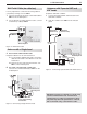
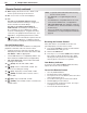
Figure 8. Connecting a VCR to an Antenna or Wall
Outlet Cable
VCR to an Antenna or
Wall Outlet Cable
Required: Two-way RF splitter, two coaxial cables, right
and left analog audio cables, either S-video or compos-
ite video cable.
Connect the incoming cable or antenna to
1. IN
on the
RF splitter.
Connect one coaxial cable from
2. OUT
on the RF
splitter to
ANTENNA IN
on the VCR back panel.
Connect one coaxial cable from
3. OUT
on the RF
splitter to
ANT 1
on the TV back panel.
Connect either an S-Video or composite video
4.
cable from
VIDEO OUT
on the VCR back panel to a
VIDEO
composite or
S-VIDEO
jack on the TV back
panel. Connect only one type of video cable;
S-Video is recommended, if available.
To use the TV speakers with the VCR, connect left
5.
(white) and right (red) audio cables from
AUDIO OUT
on the VCR to the associated
AUDIO L
and
R
jacks
on the TV back panel. If your VCR is mono (non-
stereo), connect only the white (left) cable.
HDMI
3D
GLASSES
EMITTER
AVR
AUDIO
OUTPUT
DIGITAL
AUDIO
OUTPUT
L
R
L
R
(480i / 480p / 720p / 1080i)
L
R
DVI/PC INPUT
VIDEO
Y
Pb
Pr
AUDIO
Pb
Y/ VIDEO
Pr
VIDEO: 480i/480p/720p/1080i/1080p
AUDIO: PCM STEREO
PC: VGA, W-VGA, SVGA, W-SVGA,
XGA, W-ZGA, SXGA, 720p/ 1080p
1
2
3
HDMI
IR-
NetCommand
Output / External
Controller Input
R
INPUT 3
INPUT 2
INPUT 1
S-VIDEO
INPUT 3
AUDIO
R
L
AUDIO
ANT 2 / AUX
ANT 1 / MAIN
S-VIDEO
INPUT 3
AUDIO
R
L
AUDIO
R
L
S-VIDEO
INPUT 3
VIDEO
VIDEO
ANT 1 / MAIN
ANT 1 / MAIN
AUDIO OUT
S-VIDEO
OUT
VIDEO
OUT
L
R
ANTENNA
IN
VCR
TV back panel
2.
2.
1.
4.
4.
5.
5.
3.
3.
Incoming
cable
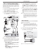
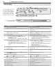
Standard Cable Box, Satellite Receiver,
or Other Device with S-Video
Required: S-Video cable and left/right analog stereo
audio cables.
Connect the cable from the outside cable or satel-
1.
lite service to
CABLE IN
or
SATELLITE IN
on the
cable box or satellite receiver.
Connect an S-Video cable from
2. S-VIDEO OUT
on
the cable box or satellite receiver back panel to
INPUT 3
S-VIDEO
on the TV back panel.
Connect left (white) and right (red) audio cables
3.
from
AUDIO OUT
on the cable box or satellite
receiver to
INPUT 3 AUDIO L
and
R
on the TV back
panel.
Note: Refer to the cable box or satellite receiver
Owner’s Guide for cable or dish antenna con-
nections to the receiver.
HDMI
3D
GLASSES
EMITTER
AVR
AUDIO
OUTPUT
DIGITAL
AUDIO
OUTPUT
L
R
L
R
(480i / 480p / 720p / 1080i)
L
R
DVI/PC INPUT
VIDEO
Y
Pb
Pr
AUDIO
Pb
Y/ VIDEO
Pr
VIDEO: 480i/480p/720p/1080i/1080p
AUDIO: PCM STEREO
PC: VGA, W-VGA, SVGA, W-SVGA,
XGA, W-ZGA, SXGA, 720p/ 1080p
1
2
3
HDMI
IR-
NetCommand
Output / External
Controller Input
R
INPUT 3
INPUT 2
INPUT 1
S-VIDEO
INPUT 3
AUDIO
R
L
AUDIO
ANT 2 / AUX
ANT 1 / MAIN
S-VIDEO
INPUT 3
AUDIO
R
L
AUDIO
R
L
S-VIDEO
INPUT 3
"6%*0
47*%&0
065
-
3
"OZ47JEFPEFWJDF
57CBDLQBOFM
$"#-&*/PS
4"5&--*5&*/
*ODPNJOH
DBCMFGSPN
XBMM
Figure 7. Connecting a device with S-Video