Projec t ion Televis Television ion Owner’s Guide WS - 5 5 517, WS - 6 5 517, WS -73 517 TM TM TV Information: Use this space to record the model and serial numbers of your television. This information is on the back of your TV. Model number Serial number visit our website at w w w. m i t s u b i s h i -t v.
CAUTION RISK OF ELECTRIC SHOCK DO NOT OPEN CAUTION: TO REDUCE THE RISK OF ELECTRIC SHOCK, DO NOT REMOVE COVER (OR BACK). NO USER SERVICEABLE PARTS INSIDE. REFER SERVICING TO QUALIFIED SERVICE PERSONNEL. The lightning flash with arrowhead symbol within an equilateral triangle is intended to alert the user of the presence of uninsulated “dangerous voltage” within the product’s enclosure that may be sufficient magnitude to constitute a risk of electric shock.
Contents Chapter 1 Television Overview TV Accessories .....................................................8 Special Features ...................................................8 Front Control Panel ...............................................9 Back Panel ..........................................................10 Important Notes ...................................................12 Chapter 2 Connecting External Devices & NetCommand® Setup ......................................
IMPORTANT SAFEGUARDS Please read the following safeguards for your TV and retain for future reference. Always follow all warnings and instructions marked on the television. 1. Read, Retain and Follow All Instructions Read all safety and operating instructions before operating the TV. Retain the safety and operating instructions for future reference. Follow all operating and use instructions. 2. Heed Warnings Adhere to all warnings on the appliance and in the operating instructions. 3.
IMPORTANT SAFEGUARDS, cont’d. 12. Power Lines An outside antenna system should not be located in the vicinity of overhead power lines or other electric light or power circuits, or where it can fall into such power lines or circuits. When installing an outside antenna system, extreme care should be taken to keep from touching such power lines or circuits as contact with them might be fatal. 13.
Our Thanks... Thank you for choosing Mitsubishi as your premier Home Entertainment provider. This Owner’s Guide describes the features and functions of your Mitsubishi widescreen, high definition TV. We urge you to examine this Owner’s Guide to become familiar with the innovative features and operations this unique television offers. The very core of our corporate philosophy is to provide our customers with the very best.
Chapter . . . 1 Television Overview TV Accessories ............................................................................8 Special Features ..........................................................................8 Front Control Panel ......................................................................9 Back Panel .................................................................................10 Important Notes .........................................................................
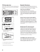
TV Accessories Special Features Please take a moment to review the following list of items to ensure that you have received everything including: Your new widescreen High Definition television has many special features that make it the perfect center of your home entertainment system, including: FF/FWD PLAY REW/REV CONNECT INFO PAUSE STOP FORMAT PIP DEVICE REC HOME DEVICE MENU PIP CH V-CHIP PIP /POP ADJUST EXCH ENTER TV MENU MUTE CANCEL SUB AUDIO SLEEP VIDEO QV 0 CHANNEL VOLUME SQV
Front Control Panel Except for SYSTEM RESET and TIMER, all of the buttons on the Front Control Panel (highlighted in gray) are duplicated on the remote control. The top row of labels show the control functions when there are no TV menus displayed on the screen. The bottom row of labels show the control functions when the TV menus are displayed on the screen or when a special function has been activated. See Remote Control Overview page 29, for further details on the functions of these buttons.
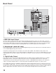
Back Panel 9. 10. INPUT 1 MONITOR OUTPUT 2 AUDIO/VIDEO 1 AUDIO 2 S-VIDEO VIDEO AUDIOLEFT/ (MONO) IR EMITTER NetCommand R AUDIORIGHT 8. COMPONENT YPbPr (480i/480p/1080i) 1 2 SERVICE WARNING CAUTION: TO MEASURE SECOND Y ANODE VOLTAGE USE A HIGH VOLTAGE METER CONNECTED FROM ANODE LEAD TO CHASSIS ONLY. DISCHARGE HIGH VOLTAGE TO CHASSIS ONLY, NOT TO EXTERNAL GROUND. Pb WARNING: HANDLE WITH CARE. HIGH VACUUM PICTURE TUBE IS DANGEROUS TO HANDLE.
Back Panel, continued 4. CableCARD™ Slot The CableCARD access card provided by your cable TV service provider is inserted into this slot. CableCARD is a nationwide standard system that allows your local cable TV provider to supply you with an access card customized to your account. This card allows the TV to receive, decode and unscramble the premium digital channels included in your cable TV subscription without the use of a cable box.
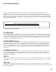
IMPORTANT NOTES Warning: Do not leave stationary PIP/POP, or letterbox images on the screen for extended periods of time. Mix the types of pictures shown. Uneven picture tube aging is NOT covered by your warranty. The normal use of a TV should include a mixture of TV picture types. The most frequently used picture types should fill the screen with constantly moving images rather than stationary images or patterns.
Chapter . . . 2 Connecting External Devices & NetCommand® Setup ..................................14 Wall Outlet Cable or Cable Box .................................................... 15 Single Analog Antenna or Separate UHF and VHF Antennas .. 16 VCR Video and Audio to an Antenna or Wall Outlet Cable ........ 17 VCR Video and Audio to a Cable Box .......................................... 18 A/V Receiver or Stereo System ...................................................
Connecting External Devices & NetCommand® Setup NetCommand is able to control many current audio and video devices by sending remote control signals from the TV to each device through IR emitters. Additionally, it is able to learn the remote control signals used by most audio video devices not already in the TV’s memory. NetCommand can automatically switch the TV along with compatible or learned Audio/Video (A/V) Receivers to the correct input for use with each device.
Connecting a Wall Outlet Cable or Cable Box Wall Outlet Cable (can be used with a CableCARD™) Cable Box (compatible with PIP/POP) Figure 1 It is very important to connect the incoming cable for your primary viewing source to ANT-1, especially for CableCARD™ use. 1. Connect the primary incoming coaxial lead cable to ANT-1 MAIN on the TV back panel. 2. For an optional secondary antenna source, connect an antenna (or cable) to ANT-2 AUX. 3.
Connecting a Single Analog Antenna or Separate UHF and VHF Antennas Single Antenna (not for use with CableCARD™) Separate UHF and VHF Antennas Figure 3 A 300-Ohm to 75-Ohm transformer is required. This is not included with the TV. Figure 4 A UHF/VHF combiner is required. This is not included with the TV. For antennas with twin flat lead 1. For antenna with twin flat leads, connect the 300-Ohm twin leads to the 300-Ohm to 75-Ohm transformer. 2.
Connecting VCR Video and Audio to an Antenna or Wall Outlet Cable VCR to Antenna or Wall Outlet Cable 5. Connect either an S-Video or Video cable from VIDEO OUT on the VCR back panel to INPUT 1 VIDEO on the TV back panel. Only one type of video cable should be connected. S-Video is recommended, if available. Figure 5 A two-way RF splitter, 3 coaxial cables, right and left audio cables and S-Video or Video cables are required. These are not included with the TV. 1.
Connecting VCR Video and Audio to a Cable Box VCR to a Cable Box cable connects to the L (left) channel. If your VCR is mono (non-stereo), connect only the white (left) cable. Figure 6 A two-way RF splitter, 4 coaxial cables, right and left audio cables and an S-Video or Video cable are required. These are not included with the TV. 1. Connect the incoming cable to IN on the RF splitter. 2. Connect one coaxial cable from OUT on the RF splitter to ANTENNA IN on the cable box back panel. 7.
Connecting an A/V Receiver or Stereo System or a Satellite Receiver or Other Device with S-Video A/V Receiver or Stereo System Figure 7 A digital audio cable and stereo audio cables are required. The digital audio cable is provided. The stereo audio cables are not included with the TV. 1. Connect a set of stereo audio cables from OUTPUT AUDIO 2 on the TV back panel to the TV AUDIO INPUT on the back of the A/V Receiver.
Connecting a DVD Player with Component Video or DVI Device DVD Player with Component Video DVI Device Figure 9 Component video cables and audio cables are required. These are not included with the TV. Figure 10 A DVI-to-HDMI cable and audio cables are required. These are not included with the TV. They may be available at your local electronics retailer. 1.
Connecting an HDMI Device or External DTV Receiver with Component Video HDMI Device Figure 11 An HDMI-to-HDMI cable is required. This is not included with the TV. It may be available at your local electronics retailer. 2 on the TV back panel, matching the correct connections: DTV Receiver to TV Back panel Connect an HDMI cable from the TV back panel to the HDMI device output. HDMI devices provide video and audio through this cable, so no other connection is required.
Connecting the IR Emitter NetCommand® IR Emitter NetCommand® Figure 13 A quadruple IR Emitter cable is included with the TV. The emitters connected to these jacks are used by the NetCommand system to control other devices such as VCR, DVD players, Cable boxes and Satellite receivers. 1. Connect the plug end of the supplied quadruple IR Emitter Cable to one of the IR Output NetCommand jacks on the TV back panel. 2.
Connecting IEEE 1394 Devices 4-Pin Style vs. 6-Pin Style There are two different types of connectors used for IEEE 1394 terminals and cables, a 4-pin and a 6-pin style. 4 pin connector 6 pin connector The 4-pin connector sends digital audio signals, digital video signals and digital control signals back and forth between devices. Your TV has three 4-pin type connection jacks available. There are two inputs on the back panel. and an additional input on the front panel.
IEEE 1394 Device Connection Styles Connection Styles There are two different connection styles that can be used when connecting IEEE 1394 devices. Use the style that fits your network of audio/video products. Direct Device-To-Device Style The IEEE 1394 offers you the capability to chain devices, unlike previous audio and video connections where you had to individually connect each device directly to the TV.
CableCARD™ Definition and Initial Screen Display CableCARD Technology Using a CableCARD CableCARD is a nationwide system standard that allows your local cable TV provider to supply you with an access card customized to your account. This card allows the TV to receive, decode and unscramble the premium digital channels included in your cable TV subscription, without the use of a cable box. It also allows your cable provider to automatically update and change your subscription.
Connecting: Helpful Hints Q My VCR (or other device) does not have two sets of stereo audio outputs. How can I connect this device’s audio to both the TV and the A/V Receiver? A. There are two solutions: 1. Connect the single set of stereo audio outputs to the TV only. Use Edit NetCommand® to change the setup of this device. In the Connection screen of “Change” make sure both audio and video for the TV input are checkmarked and neither the audio or the video for the AVR input are check marked.
Chapter . . . 3 NetCommand® Setup and Editing NetCommand® Pre-Memorized Devices .................................... 28 Remote Control Functions: Overview ..........................................29 Remote Control Functions: Operation, Care, Sleep Timer........ 30 NetCommand® OnScreen Buttons.............................................. 31 Menu System ............................................... 32 3D Graphical NetCommand® Initial Setup .........................................................
NetCommand® Pre-Memorized Devices Below is a list of several manufacturers devices tested and shown to be compatible with NetCommand. These devices can be controlled without changing the setting of the remote control from TV to another product. NetCommand may be able to operate additional models since many manufacturers use the same control signals to operate some or all of the models they offer. This chart lists only the models that have been tested with NetCommand.
Remote Control Functions: Overview Figure 1, following page 1. Slide Switch: Selects A/V product to be controlled by the remote control. 2. Numbers: Individually selects channels or enters information into menus. 3. POWER: Turns power on and off for TV and other A/V products. 4. SQV (SuperQuickView™): Scans through memorized lists of favorite channels. 5. QV (QuickView™): Switches between the current channel and last channel viewed. 6.
Remote Control Functions:Operation, Care, Sleep Timer VCR CABLE/DBS/DTV TV DVD AUDIO 1 2 1 2 3 4 5 6 Care POWER 3 For Best Results from the Remote Control: GUIDE 7 • Be within 20 feet of the equipment. 9 9 8 SLEEP 4 0 SQV 5 10 QV • Do not press two or more buttons at the same time unless instructed to do so. VIDEO DEVICE CHANNEL VOLUME 11 AUDIO 6 7 12 8 MUTE 13 ENTER 14 EXCH ADJUST TV MENU • Avoid dropping on hard surfaces.
NetCommand® On-Screen Buttons To use the TV’s NetCommand feature, the manufacturers of the devices that are connected to the television need to be defined during the Initial NetCommand setup. The TV can also learn the remote control IR code signals for most non-defined devices. During the initial setup, every available device is assigned to a specific input of the TV and/or A/V Receiver. Changes to the inputs or names are made through the Edit NetCommand screens.
3D Graphical Menu System Your TV also has Mitsubishi’s exclusive 3D Graphical on-screen operating system, which provides onscreen information for menu choices and changes, using the TV’s remote control. Remote Control Buttons Menu Screens The following buttons on your remote control help you navigate within the system : A picture (icon) will be highlighted on the menu screen when selected with the ADJUST arrows. You may then make changes within the menu or access sub-menus, if available.
NetCommand® Initial Setup IMPORTANT You may use your TV without setting up NetCommand. You may also set up NetCommand at a later time by choosing NetCommand from the Main menu, then selecting Initial. Welcome Screen Figure 1 When you first turn on your TV, the Welcome screen displays and asks you to select either English or Spanish as the language for the on-screen menus. The default language is English. To change Language later, use Setup in the Main Menu.
NetCommand® Initial Setup, continued Review Screen Finish Screen Figure 4 Figure 5 After you have made your device choices, the Review Screen will display. It is important to review the settings to ensure that they are correct. If necessary, you can use
Edit NetCommand®, Adding an A/V Receiver A/V Receiver Screen Figure 6 If your A/V Receiver manufacturer was not listed, and you selected “None” during the initial NetCommand Setup you may add the A/V Receiver and have NetCommand learn its remote controls functions. Either select Edit from the Finish screen or if you have finished the initial setup, go to the Main menu, select NetCommand, then press ENTER. The Edit NetCommmand screen will display, select Add.
Edit NetCommand®, Adding an A/V Receiver, continued A/V Receiver Input Learn Screen A/V Receiver Learn Screen Figure 8 Figure 9 NetCommand can now learn the remote control signals used to select each input on the A/V Receiver. 1. Press ADJUST or on the TV remote to select the check box for each function to be learned. 1. Press ADJUST or on the TV remote to select the check box for each function to be learned. 2.
Edit NetCommand®, Adding an A/V Receiver, continued Name Screen Monitor Out to AVR Screen Figure 10 Figure 11 The Name screen allows you to change the default name for the A/V Receiver to a custom name of up to eight characters (including a blank space), selecting from letters, numbers, and nine different characters. Using the TV’s remote, press ADJUST or to select each letter, then press ENTER to move to the next position. Press CANCEL to delete the current letter and move back one character position.
Edit NetCommand®, Adding Devices Mitsubishi’s NetCommand allows you to edit your home theater configuration. You can add new devices, change device settings and connections, delete devices and learn remote control IR signals not already in NetCommand memory. Edit NetCommand Figure 13 If you selected Edit when you were at the Finish screen, the Edit NetCommand screen displays. There are five possible choices from this screen. They are: Initial: Start the setup at the beginning.
Edit NetCommand®, Adding Devices, continued Add Screen Figure 14 Select “Add” from the Edit NetCommand screen, and the New Device screen will display. Select the device type that you would like to add. You may add your A/V Receiver (if not added in Initial setup) Cable Box, Camcorder, DBS, DVD, Laser Disc and VCR. At the next screen, choose the manufacturer.
Edit NetCommand®, Adding Devices, continued [Device] Learn Screen Figure 16 Shown only if “Learn” was selected (Figure 15) 1. Press ADJUST , , or to select the check box for each function to be learned. 2. Press ENTER and the function name will begin to flash to confirm the ready-to-learn status. 3. Press the button on the device’s remote control that corresponds to the selected function. A check mark will appear and the function name will stop flashing. This confirms the signal learned status.
Edit NetCommand®, Adding Devices, continued The screens described below may not be necessary for your device setup. If it does not display automatically onscreen, it is not required. Connection for [Device] Screen RF Connection for Cable Screen Figure 19 Figure 21 This screen allows the TV to learn the connection between device(s) and input(s). Inputs 1-3, Components 1 & 2, and/or the inputs for the A/V Receiver all need to be checked, if connected.
Edit NetCommand®, Changing, Deleting Devices, Finish Screen Change Screen Finish Screen Figure 23 Figure 25 Selecting Change from the Setup menu screen, displays the Change screen. To change a device, select the device by name, not type. You can change the name or input connections to the TV and A/V Receiver. If “Other” is selected for the manufacturer then you can also “Learn”. The rest of the screens that follow are the same as when you Add a device.
Device Selection Menu When you press DEVICE on the TV’s remote control, the Device Selection menu (Figure 26) displays. If NetCommand® has not been set up, the Device Selection menu allows you to select an input for viewing. If NetCommand is set up, the Device Selection menu allows you to select the device for viewing, select audio from the TV speakers or A/V Receiver, power compatible devices On or Off, and verify the destination of signals.
Using the Device Menu Button to Display Menus Device Menu Pressing the remote control’s DEVICE MENU button displays the menu for the current device source. IR Controlled Devices/IEEE 1394 Menus For a NetCommand compatible traditional IR controlled or an IEEE 1394 device, pressing DEVICE MENU once or twice will display the menu for that device. While the menu for the device is displayed, press ADJUST , , or and ENTER to navigate the screen.
Chapter . . . 4 IEEE 1394 Devices and NetCommand® Controlled Recordings Adding IEEE 1394 Devices Automatically .................................... 46 IEEE 1394 Compatibility ................................................................ 48 Using the Guide Button to Display ChannnelView™ and Menus ......................................................................................49 NetCommand® Controlled Recordings ......................................50 Direct VCR Recording .......................
Adding IEEE 1394 Devices Automatically Adding IEEE 1394 Devices Automatically When an IEEE 1394 device is connected into the TV network and is powered On, the new device will automatically announce its presence. This process is called device discovery and can take up to 1 minute. Some non-audio/video or non-compatible IEEE 1394 devices, such as Personal Computers (PCs), may not announce their presence to the TV.
Adding IEEE 1394 Devices Automatically, continued IEEE 1394 Device Type Screen Figures 3 and 4 If the new IEEE 1394 device is also connected using analog inputs, you will need to define the device type. Select the type of device, such as a VCR. Once the device type is selected, then the Device screen is displayed so the manufacturer can be selected. If the manufacturer is listed, then you may be able to control this device while it is operating as an analog VCR.
IEEE 1394 Devices Compatibility Compatible IEEE 1394 Devices It is possible to connect devices to the TV that have IEEE 1394 connectors but are not compatible with the TV or with the NetCommand® control system. Areas of compatibility to consider are: 1. Digital Video Signals The TV is able to decode MPEG2 video. Other types of digital video, such as DV video provided by some camcorders, must be decoded by the source device and sent to the TV as analog video or S-Video.
Using the GUIDE Button to Display ChannelView™ and Menus The GUIDE Button Depending on the device you are currently viewing, pressing GUIDE allows you to see different program guides or menus. Devices (1394 or IR Controlled) For NetCommand compatible satellite receivers and some cable boxes, GUIDE will display the on-screen programming guide for the receiver or cable box. Press ADJUST , , or and ENTER to navigate the displayed Guide.
NetCommand® Controlled Recordings Record To Setup Recording Now Figure 8 Can be used when viewing Antenna 1 or 2, an IEEE 1394 device, or a non-recording traditional device. Your TV is able to start and stop recordings automatically and send the signals from one external playback device to another external recording device. It is also able to convert digital channels and IEEE 1394 device signals to analog signals that can be recorded on NetCommand compatible analog VHS and S-VHS VCRs.
NetCommand® Controlled Recordings, continued Record List Screen Track List Screen Figure 9 Figure 10 To see a list of all currently programmed recordings, press GUIDE while viewing the Record To screen. A maximum of 32 recordings can be scheduled. To cancel a recording on the Record List, press ADJUST or to select the recording, then press CANCEL. To page through the list, press CH or . When viewing an A/V Disc, press GUIDE to display its Track List.
Direct VCR Recording Direct VCR Recording from an Antenna Restrictions for Traditional VCRs If turned On, the TV must be tuned to the Source or Cable Source: Device. Pressing REC (record) on the TV’s remote control will function the same way as pressing the record button on the VCR’s remote control or front panel. 1. Press DEVICE on the TV’s remote to display the Device Selection menu. Highlight the traditional VCR and press POWER to turn on the VCR.
NetCommand® Controlled Peer-to-Peer Connections What is a Peer-to-Peer Connection? Setting up a Peer-to-Peer Connection Figure 11 A peer-to-peer connection is a current connection and cannot be setup as a delayed connection. A peer-to-peer connection allows the IEEE 1394 devices in your TV network to talk to each other without the further need of TV intervention once the peer-to-peer connection is established. To establish a peer-to-peer connection: 1. Press REC on the TV remote.
IMPORTANT NOTES WARNING: Do not leave stationary or letterbox images on-screen for extended periods of time. Mix types of pictures shown. Uneven picture tube aging is NOT covered by your warranty. The normal use of a TV should include a mixture of TV picture types. The most frequently used picture types should fill the screen with constantly moving images rather than stationary images or patterns.
Chapter . . . 5 TV Menu Screen Operations Main Menu Choices .......................................................................56 Setup Menu ....................................................................................57 NetCommand® Menu ....................................................................59 Antenna Menu ................................................................................ 60 Time Menu ...................................................................................
Main Menu Choices Setup Time Figure 1 Figure 4 Use the Setup menu to select English or Spanish as the language for the menus and on-screen displays. Adjust Color Balance Automatically or manually (PerfectColor™) using six colors, Magenta, Red, Yellow, Green, Cyan and Blue. Reset the Color Balance to the factory default settings. Align the focus (convergence) of the TV’s projected light beams or reset the focus to the factory default settings.
Setup Menu Setup Menu Figure 8 Figure 9. PerfectColor Menu, Manual Color Correction Figure 8. Setup Menu, Language option Language Display the on-screen menus in either English or Spanish (Español). The first time you powered On your TV, you were requested to select an on-screen menu language. If you choose to change the selection, all menu text will immediately switch to the language of your choice.
Setup Menu, continued Convergence, continued Figure 10 When the Red and Blue crosshairs are properly converged, the center-screen crosshairs will appear white. You can press ADJUST , , or to move the Red and Blue crosshairs. Press VIDEO to switch between Red and Blue. Press AUDIO for the Advanced Convergence screen. 7. You may also press INFO to display detailed instructions on using the Advanced Convergence. Then press INFO or MENU to return to the Advanced Convergence menu.
NetCommand® Menu NetCommand Menu Remote Control Transport Buttons Figure 13 Transport buttons (rewind, play forward, stop, pause and record) on the remote control are located in the bottom section of the remote control. REC STOP PAUSE CONNECT PLAY FF/FWD REW/REV Transport Buttons STOP Default Digital Record Device Figure 13. NetCommand menu Detailed information for setting up and editing the NetCommand menu is found in Chapter 3.
Antenna Menu Antenna Menu Figure 16 Channel For additional Channel editing, press ADJUST or to select the channel or press CH or for channels already in memory. Channels can also be selected by using the number buttons. To immediately tune to the listed channel, press ENTER after entering the number(s). Figure 16. Antenna Menu Antenna Menu The Antenna Menu options are available for use with analog and digital channels on Antenna-1 and Antenna2.
Antenna Menu, continued SQV (SuperQuickView™) SQV (SuperQuickView™) Using The Menu Screen Using The Remote Control Figure 17 SQV (SuperQuickView™) allows you to put together lists of your favorite channels from Antenna-1 and Antenna-2. You can store channels in any of the 9 different SQV memory banks. You can also store the same channel in multiple memory banks. Once you have added a channel to an SQV memory, “SQV” and the memory bank number will appear under the tuned channel number on the TV screen.
Time Menu Setting the Clock You may choose to set the clock that your TV will use manually or automatically. Manual Figure 18 To manually set the clock, you need to select the current time, including AM or PM, current date, time zone for your area and the Daylight Savings time setting. (XDS) time data, typically a PBS channel. The Auto selection will automatically retrieve the correct time and date information from this channel.
Captions Menu Captions Menu Figure 20 For analog channels, broadcasters can send either Standard or Text closed captioning. Standard Closed Captions follows the dialogue of the characters onscreen and displays in a small section of the screen. Text Closed Captions often contain information such as weather or news and covers a large portion of the screen. On digital channels, broadcasters can send up to 6 different captioning selections.
Captions Menu, continued Fonts You can customize the text of digital captions by selecting the font of your choice.
V-Chip Lock Menu V-Chip Select V-Chip to Block or Allow programs based upon rating signals sent by the broadcaster. The TV comes from the factory with the V-Chip Lock in the Off setting. You can turn the V-Chip On within the V-Chip Menu or you can use the V-CHIP button on the remote control to conveniently turn the V-CHIP On or Off. The factory preset is TV-PG for TV ratings or PG for movie ratings, allowing only programs rated TV-PG/PG or lower.
V-Chip Lock Menu, continued V-Chip Signal Information When provided by the broadcaster, V-Chip ratings can be used to control which programs can be viewed or will be blocked. When V-Chip ratings are sent, you will see the ratings when you change the channel or when you press the INFO button on the remote control. Both TV and Movie ratings will display. TV ratings apply to programs and movies developed for TV and may have supplemental blocking by content categories.
V-Chip Lock Menu, continued Lock By Time Front Button Lock Figure 25 Front Button Lock allows you to disable controls on the front panel to prevent anyone from changing settings by accident. Lock by Time allows you to lock the entire TV during specific hours. During the Lock Time, you must use your passcode to view the TV. To enable the lock: or to select On or Off, then press Press ADJUST ADJUST to move to the Lock Time box.
AudioVideo Menu AudioVideo Figure 26 TV Speakers Select On to use the TV’s internal speakers. Select Off when sending the sound through a separate stereo system or surround sound A/V receiver. When NetCommand® is enabled, selecting the A/V Receiver icon from the Device Selection menu automatically turns Off the TV speakers. See the NetCommand menus for further instructions. Note: To prevent damage from a sudden increase in volume, make sure the TV volume is set to low before setting speakers to On.
A/V Setting Descriptions NOTE: The effects of the Audio Settings of Bass, Treble, Balance and Surround affect the sound heard through the TV speakers only. Analog and Digital Audio Setting A slider will display on-screen for most settings. When the slider is displayed it has a numeric value, where 63 is the maximum, 31 is the mid-point and 0 is the minimum. ◊ Bass Enhances or reduces low-pitch sound. ◊ Treble Enhances or reduces high-pitch sound.
A/V Setting Descriptions, continued Video Settings ◊ Contrast Provides a slider to adjust the white-to-black level. Low contrast shows a variety of shades in darker images, while high contrast shows darker images more uniformly black and makes colors appear more vibrant. In most home lighting situations, a medium contrast looks best. High contrast is good for brightly lit environments. ◊ Brightness Provides a slider to adjust the overall brightness of the picture.
Chapter . . . 6 Special Features Display Formats ............................................................................72 Operation of PIP and POP ............................................................. 74 Device Menu with NetCommand® ...............................................75 Appendix A: Bypassing the V-Chip Lock .....................................77 Appendix B: High Definition Input Connection Compatibility ... 79 Appendix C: Remote Control Programming Codes ...................
Display Formats This is a widescreen TV (also known as a 16:9 TV). This shape reflects the new types of images available from HDTV and many DVDs. There are still many older style narrow screen images (called 4:3 aspect ratio) you will encounter. While there will never be a perfect solution for displaying a narrow image on a wide screen, Mitsubishi offers several display formats to choose from. Press FORMAT on the TV remote control to cycle through the available display formats.
Display Formats, continued ORIGINAL SIGNAL Anamorphic DVD ORIGINAL SIGNAL Non-anamorphic or SD 4:3 TV Display TV Display Standard Standard (not recommended, distorted) (recommended) not available for HD, SD 16:9 or analog 1080i Expand not available for HD, SD 16:9 or analog 1080i Expand (recommended for letterboxed) (not recommended, distorted) not available for HD, SD 16:9 or analog 1080i Zoom not available for HD, SD 16:9 or analog 1080i Zoom (not recommended, distorted) (recommended for an
Operation of PIP and POP You can display programs from analog channels, analog inputs or devices as Picture-In-Picture (PIP) and PictureOutside-Picture (POP). The TV has a second analog tuner for non-scrambled analog channels received on Ant-1 and will display them as the PIP/POP sub-pictures. Digital channels and devices can be shown as the main picture but cannot be the sub-picture. PC screens can be viewed in the side-by-side mode. Press PIP/POP to activate.
Device Menu with Net Command® NetCommand Compatible Traditional Devices (Analog) When Device Selection Menu is Displayed and the Device is Highlighted (Yellow Outline) Remote Control Button A/VReceiver VCR DVD Cable Box/DBS POWER Power On/Off (toggle) Power On/Off (toggle) Power On/Off (toggle) Power On/Off (toggle) GUIDE Changes between digital and analog audio Changes VCR inputs n/a Changes antenna inputs (RCA model DTC-100 only) FORMAT n/a n/a Changes output between interlaced and prog
Device Menu with Net Command®, continued IEEE 1394 Devices (Digital) When Device Selection Menu is Displayed and the Device is Highlighted (Yellow Outline) Remote Control Button Tuner/ Cable box/DBS A/VDisc D-VCR Amplifier POWER Power On/Off (toggle) Power On/Off (toggle) Power On/Off (toggle) Power On/Off (toggle) GUIDE n/a n/a n/a n/a FORMAT n/a n/a n/a n/a When an IEEE 1394 Device is Viewed or Played Remote Control Button Cable/DBS A/V Disc D-VCR CH up/down Channel up/down Skip
Appendix A: Bypassing the V-Chip Lock Lock Bypass Instructions Have Been Filed for Future Reference Bypassing the V-Chip Lock After you set the lock, you need your passcode to view a V-Chip locked program, view the locked TV, cancel the lock, or enter the V-Chip Lock menus. If you forget your passcode, you can view the locked TV without entering your passcode. This is done by pressing the number 9 and QV buttons on the TV remote control at the same time, when your passcode is requested.
This page intentionally blank 78
Appendix B: High Definition Input Connection Compatibility Component-1 and Component-2 Inputs These inputs are compatible with component video signals from standard DVD players and other equipment sending a standard NTSC component video signal (480i). These inputs are also compatible with newer DVD players sending 480p and are compatible with signals from digital TV receivers that send 1080i component video signals. This also applies to next generation video game consoles sending 480p or 1080i.
Appendix C:Remote Control Programming Codes IMPORTANT The remote control may return to its initial setting when the batteries are changed. You may need to reprogram. Programming the Remote to Control NetCommand A/V Products 1. Move the slide switch at the top of the remote to the TV position. 2. Press and hold POWER on the remote control. 3. Enter the three digit code of 935, and then release POWER. 4.
Appendix C: Remote Control Programming Codes, continued Cable Boxes, continued VCRs SCIENTIFIC ATLANTA SIGNATURE SLMARK SPRUCER STARCOM STARGATE TELEVIEW TOCOM TOSHIBA UNIKA UNITED CABLE UNIVERSAL VIDEOWAY VIEWSTAR ZENITH VCR Brand MITSUBISHI AKAI AUDIO DYNAMIC BELL&HOWELL BROKSONIC CANON CITIZEN CRAIG CURTIS MATHES DAEWOO DBX DIMENSIA EMERSON FISHER FUNAI GE GO VIDEO GOLDSTAR HITACHI INSTANT REPLAY JVC KENWOOD LXI MAGNAVOX MARANTZ MARTA MEMOREX MGA MINOLTA MULTITECH NEC OLYMPIC OPTIMUS ORION PANASONIC P
Appendix C: Remote Control Programming Codes, continued IMPORTANT Some manufacturers may change their products, or they may use more than one remote control system. If this is the case, your remote control may not be able to operate your VCR, DVD, cable box, satellite receiver, or A/V receiver. After entering the correct codes in each position of the remote control, use the slide switch to select which product will respond when an operational button is pressed.
Appendix D: On Screen Information Displays When you turn on the TV, change Devices, change Channels or when you press the INFO button on the remote control the TV will display the current status. Below are the most common displays; please note that seldom or never do all of the different status indicators appear at the same time. Analog Program 1. Antenna or Device being viewed 3 2 2. Analog channel being received: If antenna being viewed 3. Analog channel name (only if manually programmed) 4.
Appendix E: NetCommand® Specialized Device Keys A/V RECEIVER X CABLE or DBS X VCR DVD Function Name on TV Remote X LEARNING SCREEN CHECKBOX NAME Power* X X X X Power On or Power On/Off POWER** X Power (Off)* Power Off POWER** Volume Up Volume Up VOLUME X X Volume Down Volume Down VOLUME X Mute Mute MUTE X Analog to Digital* Analog/Digital Switch GUIDE** X Digital to Analog* Digital/Analog Switch GUIDE** X Input (1-7) AVR Input Select Automatic (when device is selected
Appendix F: Cleaning and Service Cleaning General Cleaning Warnings: Normally, light dusting with a dry, non-scratching duster will keep your TV clean. If cleaning beyond this is needed, please use the following guidelines: • DO NOT allow liquid to enter the TV through the ventilation slots or any crevice. First, turn off the TV and unplug the power cord from the power outlet.
Appendix G: Diamond Shield™ Removal for Models WS-55517 and WS-65517 The Diamond Shield for the WS-55517 and WS-65517 comes installed by the factory. If you prefer, it can be removed using the steps on these pages. The molding clips can only be removed as described, incorrect removal of the molding clips can damage the Diamond Shield. For the WS-55517 and WS-65517: 1. Snap open the molding clips on the right and left side of the screen. The side closest to the screen opens.
Appendix G, continued: Diamond Shield™ Installation for Model WS-73517 The Diamond Shield for the WS-73517 comes in a separate package. To install: 1. Snap open the molding clips on the right and left side of the screen. The side closest to the screen opens. Unsnap the top, bottom and middle, preferably in that order (the clips are fixed to the TV and are not detachable). Do not force the clips, they should open easily. 2. Carefully remove the Diamond Shield from the protective packaging.
Appendix H: Cabinet Separation for Models WS-65517, WS-73517 For Mitsubishi Dealers and Service Personnel Only The cabinets for Mitsubishi projection television models WS-65517 and WS-73517 have been assembled in two pieces. These pieces may be separated to allow for easier delivery and setup. To safely separate and reattach the cabinet, follow the instructions below. This projection television weighs over 320 pounds and has many sensitive components.
Troubleshooting Problem Possible Solution 1. The TV remote control does not work. • Check that the batteries are installed correctly. • Check that the select switch is set to “TV”. • Be no further than 20 feet from the TV when using the remote control. • Program the remote control to operate the TV (Appendix C). 2. The TV takes several seconds to respond. • It is normal for digital channels to take longer to tune in. • Press ENTER after a channel number to avoid delays.
Troubleshooting, continued Problem Possible Solution 18. TV functions do not respond to the remote control or to front panel control and will not Power Off. • Use the System Reset button as explained at the end of this section. 19. Name options not available for some channels • Only memorized analog channels can be named. 20. When viewing a stopped VCR, white lines are rolling on the screen. • Turn off video mute for the VCR. • Begin playing the tape. • Change the VCR input to the antenna input.
Troubleshooting, continued Problem Possible Solution 30. A program recorded on your TV is distorted when played on a 4:3 TV. • TV was set to Anamorphic when program was recorded. Record programs in Cropped mode if playing back on a 4:3 TV. 31. Excessive digital artifacts. • The IEEE 1394 cable is too long (15 feet between devices is the maximum length). • There may be a slow device in the middle of the IEEE 1394 network.
Troubleshooting, continued Problem Possible Solution 43. An IEEE 1394 device has been plugged in but does not appear in the Device Selection menu (not discovered). • The IEEE 1394 connection to the TV or another device is not secure or is loose. • The IEEE 1394 device is not powered on. • A device in the IEEE 1394 chain is not powered on - turn on all the devices. • The device discovery can take as long as a minute to initiate. • IEEE 1394 cable is too long (maximum of 15 feet between devices).
Additional Information From time to time, Mitsubishi may offer software updates to expand the features or operation of this TV. When these updates are available they will be announced on our web site, Mitsubishi-tv.com. If you return your Owner’s registration card, with your model and serial number, you may receive written notification of available software updates. Demo Mode This TV has a demo mode for use in a retail store.
Single Analog Antenna 16 Separate UHF and VHF Antennas 16 Wall Outlet Cable 15 VCR Video and Audio to Index an Antenna 17 a Cable Box 18 a Wall Outlet Cable 17 A A/V (Audio/Video) Disc Search 51 Memory Reset 68 Menu 56, 68 Receiver Screens 35-37 Reset 9 Settings 68 Setting Descriptions 69-70 Additional Information 93 Advanced Convergence 58 Analog Audio Settings 69 Captions 63 Antenna Menu 56, 60-61 Appendix A: Bypassing the V-Chip Lock 77 B: High Definition Input Connection Compatibility 79 C:Remote Cont
H R HDMI™ Device Connections 11 Record List Screen 51 Record To Screen 50 Recordings 50, 51, 52 Remote Control Buttons 32 Functions 29, 30 I Icon Order 59 IEEE-1394 Adding Automatically 46 Connection Screen 47 Devices Compatibility 48 Device Connection Styles 24 Device Type Screen 47 Finish Screen 47 Input/Output 10 New Device Screen 46 Important Notes 12, 54 Safeguards 4 IR Code for [Device] Screen 41 IR Output-NetCommand® 11 L Language 57 Lock By Time 67 M Menu Choices (also see individual name) 56
Mitsubishi Projection TV Limited Warranty MITSUBISHI PROJECTION TELEVISION LIMITED WARRANTY MITSUBISHI DIGITAL ELECTRONICS AMERICA, INC. (“MDEA”) warrants to the original purchaser of this television that if purchased from an authorized MITSUBISHI Audio/Video Dealer, should it prove defective by reason of improper workmanship and/or material: a. Parts. The lenticular (i.e. front picture) screen and/or the DiamondShield™ is warranted against defects in materials and workmanship for a period of 30 days.
MITSUBISHI TV SOFTWARE END-USER LICENSE AGREEMENT FOR EMBEDDED SOFTWARE IMPORTANT – READ CAREFULLY: This License Agreement is a legal agreement between you (either an individual or an entity) and Mitsubishi Digital Electronics America, Inc. (MDEA) for all software preinstalled and/or provided along with this television (“Software”). By utilizing this television and Software, you agree to be bound by the terms of this License Agreement.
Notes
LICENSOR’S SUPPLIERS DO NOT MAKE OR PASS ON TO END USER OR ANY OTHER THIRD PARTY, ANY EXPRESS, IMPLIED OR STATUTORY WARRANTY OR REPRESENTATION ON BEHALF OF SUCH SUPPLIERS, INCLUDING, BUT NOT LIMITED TO THE IMPLIED WARRANTIES OF NON-INFRINGEMENT, TITLE, MERCHANTABILITY OR FITNESS FOR A PARTICULAR PURPOSE. This product incorporates copyright protection technology that is protected by U.S. patents and other intellectual property rights.
If you have questions r egar d ing your te levi sion, call Consumer Re lations at ( 8 0 0 ) 3 3 2-2119 , or email us at M D E A S e r v i c e @ m d e a .c o m To or der r e placement or additional r e mote contr ols or Owne r ’s Guides c a l l ( 8 0 0 ) 5 5 3 -7 2 7 8 or vi sit our we bsite at w w w. m i t s u b i s h i -t v.c o m © 2005 Mitsubishi Digital Electronics America, Inc. 871D448A10 Written and Printed in the U.S.