2005 Down to1 ™ HIGH SPEED TROUBLESHOOTING V25-V27 CHASSIS V25 V25+ V25++ WS-48515 WS-55515 WS-65515 WS-55615 WS-65615 WS-73615 WS-55815 WS-65815 V27 WS-55517 WS-65517 WS-73517 MITSUBISHI DIGITAL ELECTRONICS AMERICA, INC. 9351 Jeronimo Road, Irvine, CA 92618-1904 Copyright © 2005 Mitsubishi Digital Electronics America, Inc.
V25 / V27 Chassis Down to 1 V25 / V27 CHASSIS Down to 1 - High Speed Troubleshooting TABLE of CONTENTS Safety Precautions ......................................................................................................................... 2 Cabinet Disassembly ...................................................................................................................... 3 Chassis Removal ............................................................................................................
V25 / V27 Chassis Down to 1 PRODUCT SAFETY NOTICE Many electrical and mechanical parts in television receivers have special safety related characteristics. These characteristics are often not evident from visual inspection nor can the protection afforded by them necessarily be obtained by using replacement components rated for higher voltage, wattage, etc. Replacement parts which have special safety characteristics are identified in this manual.
V25 / V27 Chassis Down to 1 CABINET DISASSEMBLY (FRONT VIEW) Typical Procedure - Disassembly will vary by model. For exact procedures by model, refer to the Service Manual. Front Cabinet Disassembly 1. 2. 3. 4. 5. 6. Remove the Speaker Grille by pulling forward. Remove the Board Front by removing screws (a). Remove 4 screws (b) holding the Screen Assembly (all models). Remove screws (c) from the Screen Assembly (65 & 73 inch models only) Unplug the CC, ZF and GR connectors from the Control Panel.
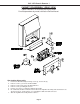
V25 / V27 Chassis Down to 1 CABINET DISASSEMBLY (REAR VIEW) Typical Procedure - Disassembly will vary by model. For exact procedures by model, refer to the Service Manual. Rear Cabinet Disassembly 1. 2. 3. 4. 5. 6. Remove the Back Board by removing screws (a), and screws (b). Remove screws (c) to remove the Board Slide. Remove screws (d) to remove the Board Shelves. Remove screw (e) holding the chassis. Remove 4 screws (f) securing the Light Box Assembly.
V25 / V27 Chassis Down to 1 CABINET SEPARATION PROCEDURE Typical Procedure - Disassembly will vary by model. For exact procedures by model, refer to the Service Manual. 65 & 73 Inch Models Cabinet Separation Procedure 1. Pull the Speaker Grill from the cabinet. 2. Unplug the CC, ZF and GR connectors. 3. Remove 4 plastic covers and screws (a) from each side of the cabinet. 4. Carefully lift the cabinet top and place it on the floor. 5. Place the cabinet bottom in the desired location. 6.
V25 / V27 Chassis Down to 1 Troubleshooting Troubleshooting Steps: 1. If the Power LED is continuously flashing or if other TV controls seem locked, perform a System Reset by pressing the front panel button or by removing and re-applying AC power. 2. If the Power LED seems abnormal, use the chart below to determine the condition. LED Indications Off Fast Blink for 70 sec.
V25 / V27 Chassis Down to 1 V25 & V27 Symptom/Cause Information Symptom Most Likely Video Problems, all Inputs & Menu bad. Audio OK PCB-SIGNAL Video&Audio Problems. All signals bad. HV is OK PCB-DM3 Analog Tuning problems. External Inputs & Digital OK PCB-SIGNAL Analog Tuning & External Inputs Problems. Digital OK PCB-TERMINAL Digital Tuning problems. Analog OK PCB-TUNER 1394 Problems PCB-DM3 Audio Problems. Speakers, Monitor A/V 1 & Audio 2 Bad PCB-TUNER Audio Problems. Speakers, Monitor A/V 1 Bad.
V25 / V27 Chassis Down to 1 DM3 TUNER FIF E2P PCB Locations & Functions SIGNAL DBF HDMI TERMINAL MAIN PCB-DM3 NetCommand PIP-P OP IEEE1394 Picture Format C ard Viewer 3:2 Pull D own OSD-Menus Line Double D igital uPC Control 480i to 480p MPEG D ecoder Audio D/A C onv. PC B-Tuner PC B-Terminal A/V Inputs A/V Selection 3D-Y/C NTSC Video Decoders Sys 5 - Learning PCB -Signal Control uPC VCJ Convergence Audio A mp Vertical Defl.
V25 / V27 Chassis Down to 1 PCB, Main Component & Connector Locations (Top View) W S-48515 W S-55515 W S-55615 W S-55815 W S-55517 W S-65515 W S-65615 W S-65815 W S-65517 W S-73615 W S-73517 MAIN 930B918001 930B918001 930B918002 930B918002 930B918002 930B918002 930B918002 930B918003 930B918002 930B918003 930B918003 W S-48515 W S-55515 W S-55615 W S-55815 W S-55517 W S-65515 W S-65615 W S-65815 W S-65517 W S-73615 W S-73517 CRTs 934C106001 934C106001 934C106001 934C106001 934C106001 934C106001 934C10600