Projection Television Models WS-55859, WS-55909, WS-65869, WS-65909, and WS-73909 AD JU CO ® visit our website at w w w. m i t s u b is h i - t v.
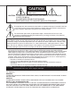
CAUTION RISK OF ELECTRIC SHOCK DO NOT OPEN CAUTION: TO REDUCE THE RISK OF ELECTRIC SHOCK, DO NOT REMOVE COVER (OR BACK). NO USER SERVICEABLE PARTS INSIDE. REFER SERVICING TO QUALIFIED SERVICE PERSONNEL. The lightning flash with arrowhead symbol within an equilateral triangle is intended to alert the user of the presence of uninsulated “dangerous voltage” within the product’s enclosure that may be sufficient magnitude to constitute a risk of electric shock.
Table of Contents IMPORTANT SAFEGUARDS ............................................................................4-5 T H A Y N O K U Thank You Letter ...............................................................................................................................................8 Unpacking Your New TV...................................................................................................................................9 Special Features ..........................................
IMPORTANT SAFEGUARDS Please read the following safeguards for your TV and retain for future reference. Always follow all warnings and instructions marked on the television. 1. Read, Retain and Follow All Instructions Read all safety and operating instructions before operating the TV. Retain the safety and operating instructions for future reference. Follow all operating and use instructions. 2. Heed Warnings Adhere to all warnings on the appliance and in the operating instructions. 3.
IMPORTANT SAFEGUARDS Continued 12. Power Lines An outside antenna system should not be located in the vicinity of overhead power lines or other electric light or power circuits, or where it can fall into such power lines or circuits. When installing an outside antenna system, extreme care should be taken to keep from touching such power lines or circuits as contact with them might be fatal. 13.
If you have questions regarding your television, call Consumer Relations at (800) 332-2119, or email us at MDEAservice@bigscreen.mea.com To order replacement or additional remote controls or owner’s guides call (800) 553-7278 or visit our website at w w w.m i t s u b ish i - t v.
Thank You Thank You Letter..............................8 Unpacking Your New TV .................9 Special Features ..............................
Part I: Thank You We at Mitsubishi Would Like to Thank You Thank You Letter To the Mitsubishi Consumer: 8 Thank you for choosing Mitsubishi as your premier home entertainment partner. The development team at Mitsubishi understands that our customers demand and expect the very best. Mitsubishi is founded on the core beliefs and philosophies that drive us to deliver products that lead the industry.
Part I: Thank You Unpacking Your New TV Special Features Please take a moment to review the following list of items to ensure that you have received everything included: 1 Remote Control 2 (2) AAA Batteries 3 (1) Digital Audio Cable 4 (1) Double IR Emitter Cable 5 (1) Quadruple IR Emitter Cable 6 Product Registration Card 7 Owner’s Guide 8 Quick Reference Card 9 NetCommand™ Guide et 10 Connection Con gur at ion Di agr ams Your new High De ni tion bi gscr een t el evi si on has many special features that
Installation Front Control Panel Functions .....12 Back Panel Functions .............. 13-14 Installation Con gur at ions and NetCommand™ Setup................15 NetCommand™ Supported Devices 16 Connecting to Your New Mitsubishi Bigscreen: Antenna or Wall Outlet Cable for Digital Broadcasts ................... 17 Analog Antenna, Wall Outlet Cable or Cable Box ......18 Analog VCR ................................19 A/V Receiver..............................20 DVD Player or S-Video VCR or Satellite Receiver ..
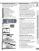
Part II: Installation Front Control Panel Figure 1. Front Control Panel. Front Control Panel Functions The buttons on the front control panel that are highlighted in gray are duplicated on the remote control. The top row of labels show the control functions when there are no TV menus displayed on the screen. The bottom row of labels show the control functions when the TV menus are displayed on the screen. See Remote Control Functions: Overview, page 60, for details on their functions.
Part II: Installation 10 Back Panel 11 1 2 12 5 6 7 9 3 8 1 4 Inputs 1-4 2 Output (Monitor and PIP) The Monitor Output sends the TV audio and video signals from Ant-A, Ant-B and Inputs 1-5 to a VCR or other analog A/V equipment. It will also send digital audio and video signals from Ant-DTV and IEEE-1394 products that are not copy protected, and convert them to analog signals. From VGA, Component 1 and 2 and Input-DTV, no signals will be sent.
Part II: Installation 10 Back Panel 11 1 2 12 5 6 7 9 3 Back Panel Functions 8 8 4 Antenna DTV (ANT-DTV) This input receives digital TV signals from a VHF/UHF antenna or unscrambled digital cable system. If the TV receives scrambled signals on this input, it will not be able to decode them. In this case, your cable company must provide a decoding box. 9 IEEE-1394 Input/Output These jacks allow the TV to connect to one or more external A/V products by means of a single cable.
Part II: Installation Installation Con gur at ions & Ne t Co mma nd™S e t up With this book you will nd f ol d- out pages t hat show 6 over vi ew d i agr ams of st andar d, pr eestablished system connections, called con gur at ions. These di agr ams speci fy t he i nput s to use on the TV and on the NetCommand™ supported Audio Video (A/V) Receivers. Later pages in this book will show details on how to connect devices to individual TV inputs.
Part II: Installation NetCommand™ Supported Devices Following is a list of devices by several manufacturers that have been tested and shown to be compatible with the NetCommand™ control system. When you use these devices you will be able to control them without changing the setting of the remote control from TV to another product.
Part II: Installation Connecting Antenna or Wall Outlet Cable for Digital Broadcasts Antenna or Wall Outlet Cable for digital broadcasts TV back panel Antenna or Wall Outlet Cable for Digital Broadcasts. For cable or antenna with coaxial lead (Figure 1) 1 Connect the incoming cable to ANT-DTV Figure 1. Antenna or wall outlet cable. Additional connection cables are not provided with the TV. They should be available at most electronic stores. on the TV back panel.
Part II: Installation Connecting an Analog Antenna, Wall Outlet Cable, or Cable Box UHF Antenna (Channels 14-69) VHF Antenna (Channels 2-13) Separate UHF and VHF Antennas (Figure 1) 1 Connecting an Analog Antenna, Cable, or Cable Box 2 Connect the UHF and VHF antenna leads to the UHF/VHF combiner. Push the combiner onto ANT-A on the TV back panel. UHF/VHF combiners are not provided with the TV. They should be available at most electronic stores.
Part II: Installation Connecting an Analog VCR TV back panel Analog Antennas or Wall Outlet Cable (Figure 1) Incoming Cable 1 1 2 3 VCR back panel 2 2 IN L Antenna L (Y/C) 1 2 1 MONITOR R R 3 One from LOOP-OUT on the TV back panel to ANTENNA IN on the VCR back panel. One from VCR back panel ANTENNA OUT to ANT-B on the TV back panel. 4 Now complete gur e 3, steps 1- 2. VIDEO OUT AUDIO IN AUDIO OUT 3 OUT Figure 1. Connecting VCR with antennas or wall outlet cable.
Part II: Installation Connecting an Audio/Video Surround Sound Receiver Connecting an A/V Receiver (Figure 1) 1 Connect a video cable from Monitor VIDEO If connecting a digital A/V Receiver with Dolby DigitalTM surround sound. Connecting an Audio/Video Surround Sound Receiver OUTPUT on the back of the TV to the TV VIDEO INPUT on the back of the A/V Receiver.
Part II: Installation Do not display the same stationary images on the screen for more that 15% of your total TV viewing in one week. Examples of stationary images are letterbox top/bottom bars from DVD or other video sources, side bars when showing standard TV pictures on widescreen TV’s, stock market reports, video game patterns, station logos, web sites, or stationary computer images. Such patterns can unevenly age the picture tubes causing permanent damage to the TV.
Part II: Installation Connecting an External DTV Receiver DTV Connectors and Adaptors (Figure 1) Connecting an External DTV Receiver The TV back panel has 5 RCA-type connectors, for the Input-DTV. The back panel of your external DTV receiver may use RCAtype connectors or BNC-type connectors. If your DTV receiver comes with BNC type connections, you will need to purchase BNC to RCA adaptors to connect the TV to the DTV receiver. These adaptors should be available at most electronic supply stores.
Part II: Installation Connecting an External DTV Receiver External DTV Receiver with RGB Video Connections (Figure 1) 1 See Appendix B, page 73, for RGB video signal compatibility information. For digital audio connections, see your DTV receiver and A/V receiver Owner’s Guides. 2 3 4 6 5 7 8 8 White Red DTV Receiver G (green) 4 R (red) 5 B (blue) 3 2 2 Incoming Antenna, or Cable.
Part II: Installation Connecting a Computer with a VGA Monitor Output TV back panel Connecting a Computer VGA MONITOR CABLE (Figure 1) 1 1 Connect VGA Monitor Out from the com2 puter to VGA on the TV back panel using a 2 VGA compatible monitor cable. See Appendix B, page 73, for VGA signal compatibility. 2 Connect the L (left) and R (right) audio 1 cables from the computer to VGA AUDIO 2 2 on the TV back panel.
Part II: Installation Warning: Do not leave stationary, toolbar, or partial images on-screen for extended periods of time. Mix the types of pictures shown. Uneven picture tube aging is NOT covered by your warranty. The VGA capability of this television is designed for occasional use ONLY. The VGA input will automatically select the “Standard” screen format and ll the screen. No other formats are available with the VGA Input.
Part II: Installation The NetCommand™ Initial Setup The NetCommand™ Initial Setup In order to use your TV’s NetCommand feature, you are going to have to provide some detailed information for the initial setup of your Mitsubishi TV. You must de ne t he manufacturer and model of the devices that you connect to the television. The inputs to the TV and A/V receiver and the names for the device are pre-de ned dur i ng Ini tial Setup, but can be changed using the Edit Setup Screen.
Part II: Installation This page has been intentionally left blank 27
Part II: Installation The NetCommand™ Setup: Setup Screens When you rst tur n on your new Mi tsubi shi TV, the Initial Setup Screens will appear. You will need to navigate through these screens and properly setup the equipment connected to the TV in order to use NetCommand. Language Screen The NetCommand™ Setup: Setup Screens Figure 1 The Language Screen is the rst scr een displayed. You will need to select the language that you would like to use.
Part II: Installation The NetCommand™ Setup: Setup Screens A/V Receiver Screen Figure 1 Cable Box Screen Figure 2 Figure 2. Cable box menu. The Cable Box Screen allows you to select the manufacturer and model of the cable box that you are currently using. For the Manufacturer, select “None” if you don’t have the device. If “Other” is selected for the Manufacturer, then NetCommand™ can not control the device (use the layer switch on the remote or use the remote for the device).
Part II: Installation The NetCommand™ Setup: Setup Screens DBS Screen The NetCommand™ Setup: Setup Screens Figure 1 The DBS (Digital Broadcast Satellite) Screen allows you to select the manufacturer and model of the satellite system that you are currently using. For the Manufacturer, select “None” if you don’t have the device. If “Other” is selected for the Manufacturer, then NetCommand™ can not control the device (use the layer switch on the remote or use the remote for the device).
Part II: Installation The NetCommand™ Setup: Setup Screens Review Screen Figure 1 While viewing the Review Screen, adding or removing checks from the checkboxes on the left will turn devices (or inputs) on or off. Finish Screen Figure 2 Figure 2. Finish menu. The Finish Screen is displayed and all selections have been nal ized. Se l ect Fi ni sh t o end Setup. If you wish to change any of the precon gur ed i nput s or name s f or the devices, select the Edit button.
Part II: Installation The NetCommand™ Setup: Edit Setup Screens The NetCommand™ Setup: Edit Setup Screens Bearing in mind that your home theater system will continually change as you add and remove components, Mitsubishi’s NetCommand also offers ease of use when it comes to editing your home theater con guration. Edit Setup Screen Figure 1 When you need to make a change to your current setup, the Edit Setup Screen makes it easy.
Part II: Installation The NetCommand™ Setup: Edit Screens Delete Figure 1 Figure 1. Delete menu. Review Figure 2 When you select Review from the Edit Screen, you will see the Review Screen. This is the same Review Screen from the Initial Setup. Figure 2. Review menu.
Part II: Installation The NetCommand™ Setup: Edit Screens Name The NetCommand™ Setup: Edit Screens Figure 1 The Name screen allows you to change the default name for each device to a custom name of up to eight characters, selecting from letters, numbers, and nine different characters. Use to select each letter, then press ENTER to move to the next letter position. Press CANCEL to delete the current letter and move back one letter position.
Part II: Installation The NetCommand™ Setup: Edit Screens Monitor Out to AVR (or VCR) Figure 1 Figure 1. Monitor Out to AVR menu. AVR to VCR Connection Figure 2 Figure 2. AVR to VCR Connection menu. This screen is displayed only if a VCR is the device for editing and an A/V Reciever is connected. This allows recording from devices only accessible from the TV, such as Ant-DTV and IEEE 1394. The AVR to VCR Connection screen allows you to conrmt he connect ion f romt he A/ VRe cei ver to a VCR.
Setup on-screen menu system .....38 Device Selection Menu..............39 PIP Selection Menu ...................40 Menu Screens (Overview)....41-42 Setup Menu........................ 43-45 Edit Setup & Icon Position ...43 Convergence .........................44 Advanced Convergence, Transport Menu, Language ..45 Antenna Menu ................... 46-47 Antenna, Memorize Channels, Channel, Memory, and Name .....................................46 Super Quick View™ ..............47 Clock Menu ...................
Part III: Setup The 3D Graphical Menu System Your TV has a special control system called NetCommand™ that will control IEEE 1394 devices and selected older devices. For instructions on operating these control features, see the NetCommand™ guide. Your TV also has Mitsubishi’s exclusive 3D Graphical on-screen operating system, which provides on-screen information for menu choices and changes (Figure 1). A picture (icon) will be highlighted when selected with the ADJUST arrows.
Part III: Setup Device Selection Menu When you press the DEVICE button on your Destination Display remote control, the Device Selection Menu The TV icon is always the destination for will appear. The Device Selection Menu the currently selected device.
Part III: Setup PIP Selection Menu Destination Section PIP Selection Menu PIP Video Section 40 Figure 2. PIP Selection menu. Selecting Device for PIP (Figure 2) When the PIP DEVICE button on the remote control is pressed, the PIP Selection Menu displays. The PIP Selection Menu is similar to the Device Selection Menu except the source for the sub picture is selected and the audio display and selection are not supported.
Part III: Setup Menu Screens (Overview) Setup Menu (Figure 1) You can add, change, review or delete device settings, change the order of icons displayed on the Device Selection Menu, select convergence adjustment, turn on or off the transport menu, and select English or Spanish as the language for the menus and on-screen displays. Figure 1. Setup menu (Figure 2) Figure 2.
Part III: Setup Menu Screens (Overview) Captions Menu (Figure 1) Display closed captions or text, choose black or gray as the background color for the closed caption area, and turn on or off the Digital Channel guide. Figure 1. Captions menu V-Chip Lock Menu Menu Screens (Overview) (Figure 2) Block or allow programing based upon rating signals sent by the broadcast station, lock by time, or enable or disable the front panel buttons. Figure 2.
Part III: Setup Setup Menu: Edit Setup and Icon Position Edit Setup Button (Figure 1) The Edit Setup button displays the Edit Setup Menu (refer to Page 32). Edit Setup provides the following options: Figure 1. Setup menu Icon Position Button (Figure 2) Icon Position allows you to arrange the device icon order on the Device Selection Menu to your preferred sequence to make the operation of the TV easier. Figure 2.
Part III: Setup Setup Menu: Convergence Convergence Convergence (Figure 1) Your Mitsubishi TV has three picture tubes which need to be aligned to properly converge the projected light beams on the screen. Each picture tube projects a single color of red, blue or green. During production, your TV was carefully adjusted to properly align these colors. However, moving the TV, or the TV’s location in relation to the Earth’s magnetic poles, or the passage of time can cause these adjustments to change.
Part III: Setup Setup Menu: Advanced Convergence, Transport Menu, and Language Advanced Convergence (Figure 1) Press INFO for help There are more than 64 line intersections, but the ashi ng br acket w i ll onl y st op at the 64 adjustment points. Transport Menu (Figure 2) Figure 2. Setup menu (Transport menu selected) The Transport Menu is used by NetCommand™ to control VCRs, DVDs, IEEE 1394 AV Disc, digital VCRs, and similar devices.
Part III: Setup Antenna Menu: Antenna, Memorize Channels, Channel, Memory, and Name Antenna (Figure 1) Antenna, Memorize Channels, Channel, Memory, Name Select Ant-A, Ant-B, or Ant-DTV. For each antenna, you can memorize, add or delete channels in memory and add channels to the SQV (Super Quick View™) list. For Ant-A and Ant-B, you can name channels. 46 Memorize Channels Figure 1. Antenna menu (Figure 1) First select either air or cable (if direct cable to TV is used), then press ENTER.
Part III: Setup Antenna Menu: Super Quick View™ (SQV™) SQV (Super Quick View™) Super Quick View™ (SQV™) Using The Remote Control Viewing and changing SQV banks using the remote control: 1 Press the SQV button. Figure 1. Antenna Menu 2 To change memory banks, press a number button within 5 seconds of SQV (Super Quick View™) pressing the SQV button.
Part III: Setup Clock Menu: Auto or Manual Clock Setting Clock Setting (Auto) (Figure 1) The Clock Setting of Auto will automatically set the day and time using Extended Data Service (XDS) time data. This data is automatically retrieved from a PBS channel or other channel carrying this service when received on Ant-A or Ant-B. Time Zone Figure 1. Clock Menu (Auto) Auto or Manual Clock Setting (Figure 1) When Auto has been selected for the Clock Setting, you need to select the correct time zone.
Part III: Setup Captions Menu: Closed Captions Closed Captions (Figure 1) The TV can display one of the following: CC1, CC2, CC3, or CC4 (Standard closed captioning signals). Text1, Text2, Text3, or Text4 (Text closed captioning signals). Figure 1.
Part III: Setup V-Chip Lock Menu: Passcode Entry (Figures 1) The rst tim e you sel ect V- Ch i pLock f rom the MAIN menu, or after you have canceled your passcode you will see the screen shown in gur e 1. Af ter set ting a passcode, the next time you select V-Chip Lock from the MAIN menu, you will see “a new” replaced by “your.” Use the number buttons on the remote control to input a four-digit passcode, then press ENTER. You can delete a number and move back one space by pressing CANCEL.
Part III: Setup V-Chip Lock Menu: V-Chip V-Chip Signal Information When provided by the broadcaster, V-Chip ratings can be used to control which programs can be viewed or will be blocked. When V-Chip ratings are sent, you will see the ratings when you change the channel or when you press the INFO button on the remote control. The V-Chip ratings information can be divided into two classi cat ions, TV Ra t ings t hat incl ude Co nt ent Ca t egor i es and Movie Ratings. These are explained below.
Part III: Setup V-Chip Menu: Lock By Time and Front Button Lock Lock By Time (Figure 1) LOCK BY TIME will allow you to lock the entire TV during speci c hour s. Use ADJUST or then use ADJUST Time” option box. to select ON or OFF to move to the “Lock Lock by Time, Lock Time, and Unlock Time Figure 1. Lock by Time menu Lock By Time and Front Button Lock (Figure 1) 52 Lock by Time locks the entire TV based upon the Lock Time and Unlock Time.
Part III: Setup Timer Menu: Setting The Timer Timer On/Off (Figure 1) Figure 1. Timer menu The TV’s clock must be set before you can set the timer. If you have not set the clock, you will see the CLOCK menu instead of the TIMER menu. The timer can be turned On or Off. When On, you need to select the time to turn on, the day to turn on, the device and the channel to display. At your preselected time, the timer will turn the TV on, and a message will be displayed, “Press a key for the TV to stay on”.
Part III: Setup A/V Settings Menu: A/V Memory Reset, Video Mute, Black Enhancement, and Audio/Video Settings A/V Memory Reset A/V Memory Reset allows you to select the device which will have the A/V Settings returned to the original factory settings. To return a device’s memory to the original factory settings, select the device and then press ENTER. Audio/Video Settings Figure 1. Audio/Video menu Audio/Video Settings Menu (Figure 1) Each of the devices has its own A/V memory.
Part III: Setup A/V Settings Menu: TV Speakers TV Speakers (Figure 1) Figure 1. Audio/Video Settings menu This selection will turn on or off the TV’s internal speakers. You may select Off when sending the sound through a separate stereo system or surround sound A/V receiver. You may also turn on or turn off TV speakers by selecting the A/V Receiver icon from the Device Selection Menu. See the NetCommand™ Guide for further instructions.
Part III: Setup A/V Setting Descriptions: Audio Audio Settings Bass enhances or reduces low frequency sound. Treble enhances or reduces high frequency sound. Balance adjusts the level of sound between the left and right speakers. A/V Setting Descriptions: Audio Surround creates simulated stereo and surround effects. Your choices are: 56 • Off: No surround effects. Use this setting when using an A/V receiver with Dolby™ Pro Logic Surround, or Dolby™ Digital Surround.
Part III: Setup A/V Setting Descriptions: Video Video Settings Contrast provides a slider to adjust the white-to-black level. Low contrast shows a variety of shades in darker images, while high contrast shows darker images more uniformly black and makes colors appear more vibrant. Brightness provides a slider to adjust the overall brightness of the picture. Sharpness provides a slider to adjust the detail and clarity. Tint provides a slider to adjust the proportion of red to green.
Operation Remote Control Functions...... 60-69 Overview.....................................60 Care and Operation ...................61 Channel Selection......................62 Sleep Timer ................................62 Operation of PIP and POP.........62 Display Formats ................... 64-65 Programming the Remote Control to Control NetCommand™ ™ A/V Products ............................66 Programming the Remote Control to Control Non-NetCommand™ ™ A/V Products ......................
Part IV: Operation Remote Control Functions: Overview Overview 17 (Following page, gur e 1) 1 2 3 4 5 Overview 6 7 8 9 10 11 12 13 14 15 16 60 Slide Switch: Select A/V product to be controlled by the remote control. Numbers: Individually select channels or enter information into TV menus. POWER: Turns power on and off for TV and other A/V products. SQV (Super Quick View™): Scan through a memorized list of favorite channels. QV (Quick View™): Switch to last channel viewed.
Part IV: Operation Remote Control Functions: Care and Operation Operation Installing the Batteries: 1 (Figure 2) 3 2 4 5 11 32 14 12 1 6 7 8 9 10 13 2 15 16 17 18 2 23 22 24 25 19 26 28 For Best Results from the Remote Control: CONNECT 29 30 3 Figure 1. The remote control functions. 2 Care and Operation Be within 20 feet of the equipment. Do not press two or more buttons at the same time unless instructed to. Do not allow to get wet or become heated.
Part IV: Operation Remote Control Functions: Channel Selection and Sleep Timer Channel Selection For Ant-A or Ant-B Channels: Enter three numbers (for channel 2, press 002). Channel Selection, Sleep Timer, Operation of PIP and POP or Press the channel number and ENTER (for channel 2, press 2, then ENTER). or Enter the channel number and wait four seconds. The TV will change automatically.
Part IV: Operation Remote Control Functions: Operation of PIP and POP Changing PIP/POP Device MAIN PICTURE Side-by-Side Press PIP DEVICE to change the PIP or POP picture source device. A menu similar to the Device Selection Menu will be displayed. Changing PIP/Side-by-Side Channels Press PIP CH to scroll up and down through memorized channels on Ant-A and Ant-B.
Part IV: Operation Non-Anamorphic Picture (4:3) Display Formats 1 64 Anamorphic Widescreen Picture (16:9) 1 2 2 3 3 4 4 5 5
Part IV: Operation Remote Control Functions: Display Formats 1 2 This is a wide screen TV (also known as a 16:9 TV). This shape re ect s t he new types of images available from HDTV and many DVDs. There are still many older style narrow screen images (called 4:3 aspect ratio) you will encounter. While there will never be a perfect solution for displaying a narrow image on a wide screen, Mitsubishi offers several display formats to choose from.
Part IV: Operation Programming the Remote Control to Control NetCommand™ A/V Products To Program the Remote to Control NetCommand A/V Products: (See NetCommand Supported Devices, page 16, for the list of A/V products supported by the NetCommand System.) 1 2 Programming Remote Control 3 66 4 Move the slide switch at the top of the remote to the TV layer. Press and hold the POWER button on the remote control. Enter the three digit code of 935, and then release the POWER button on the remote control.
Part IV: Operation Programming the Remote Control to Control Non-NetCommand™ A/V Products To Program the Remote to Control Other Brands of Audio and Video Products: 1 2 3 4 Move the slide switch at the top of the remote to the product you want to control. Press and hold the POWER button on the remote control. Enter the rst thr ee di gi t code li st ed for your equipment, and then release the POWER button on the remote control. Point the remote control at the equipment and press the POWER button.
Part IV: Operation Programming the Remote Control to Control Non-NetCommand™ Programming the Remote Control to Control Non-NetCommand™ After entering the correct codes in each posiA/V Products 68 Figure 4. Programming the remote to control your DVD/ LDP. tion of the remote control, use the slide switch to select which product will respond when an operational button is pressed.
Part IV: Operation Remote Control Functions: Special Functions When your remote control has been Programmed to operate another manufacturer’s product, the function performed on each layer can vary.
Warning: Do not leave stationary or letterbox images on-screen for IMPORTANT NOTES extended periods of time. Mix the types of pictures shown. Uneven picture tube aging is NOT covered by your warranty. 70 The normal use of a TV should include a mixture of TV picture types. The most frequently used picture types should ll the screen with constantly moving images rather than stationary images or patterns.
Appendix A: Bypassing the V-Chip Lock Appendix A: Bypassing the V-Chip Lock Lock Bypass Instructions Have Been Filed for Future Reference Bypassing the V-Chip Lock After you set the lock, you need your passcode to view a V-Chip locked program, view the locked TV, cancel the lock, or enter the V-Chip Lock menus. When entering the V-Chip Lock menu, this process deletes your old passcode and prompts you to enter a new passcode. Pressing HOME at this time will cancel the entire passcode.
This page has been intentionally left blank
Appendix B: Input Connection Compatiblity Component-1 and Component-2 Inputs INP-DTV This input is compatible with most standard DTV and satellite receivers with component video (YPbPr) outputs. Compatible DTV signals are SDTV 480i/480p, and HDTV 1080i. All other DTV signals, such as 720p, need to be converted by the DTV receiver to one of the compatible signal types. Please check the DTV receiver speci cat ions bef or e connecting.
Appendix C: Remote Control Programming Codes Appendix C: Remote Control Programming Codes A/V Receivers 74 Mitsubishi . .. .. . .. .. .. .. .. Admiral . .. .. .. Aiwa. .. .. .. .. Denon . .. .. .. Fisher . .. .. .. Gerrard . .. .. .. Harman Kardon . Jensen . .. .. .. JVC . .. .. .. .. Kenwood . .. .. Magnavox . .. .. Marantz . .. .. Mclintosh . .. .. Nakamichi . .. .. Onkyo . .. .. .. Optimus . .. .. Panasonic . .. .. Philips . .. .. .. Pioneer . .. .. .. Quasar . .. .. .. RCA . .. .. .. .. Sansui . ..
Appendix D: Cleaning and Service Cleaning Normally, light dusting with a dry, non-scratching duster will keep your TV clean. If cleaning beyond this is needed, please use the following guidelines: First, turn off the TV and unplug the power cord from the power outlet. Screen behind the Diamond Shield™: Follow the instructions for the top and sides, however, wipe gently in an up and down motion, following the grooves in the screen. Clean the entire screen evenly, not just sections of the screen.
Appendix D: Cleaning and Service Service If you are unable to correct a problem with your TV, consult your Mitsubishi dealer or a Mitsubishi Authorized Warranty Service Center. Appendix D: Cleaning and Service DO NOT adjust any controls other than those described in this Owner’s Guide. DO NOT remove the protective back cover of your TV. Menus not described and shown in this owner’s guide are designed for Factory use and for Authorized Service Personnel.
Appendix E: Diamond Shield Instructions Diamond Shield™ Installation for Models WS-55859 The instructions below will lead you through the & WS-65869 Diamond Shield installation process. Included in the Diamond Shield package are the following items: For model WS-65869 only. (1) Diamond Shield™ (2) molding clips 2 Begin by inserting the shield, sliding it into the channels, starting at one side.
Appendix E: Diamond Shield Instructions Diamond Shield™ Installation for Models WS-55909, The instructions below will lead you through the WS-65909 and, WS-73909 Diamond Shield installation process. Included in the Diamond Shield package are the following items: For models WS-65909 and WS-73909 only. Appendix E: Diamond Shield™ Installation (1) Diamond Shield™ (2) molding clips 78 2 1 Carefully remove the Diamond Shield™ from the protective packaging. Wipe off any dust with a lint-free cloth.
Appendix F: Cabinet Separation Cabinet Separation for Model WS-65869 For Mitsubishi Dealers and Service Personnel Only 1 The following steps should be performed by two people: 1 Remove the decorative Plastic Covers (2) on each side of the cabinet and then remove the exposed Screws (2) on each side. 2 Carefully lift the Cabinet-Top straight up until the Brackets are clear from the Cabinet-Bottom. 2 3 Carefully place the Cabinet-Top on the oor .
Appendix F: Cabinet Separation Cabinet Separation for Models WS-65909 and WS-73909 Appendix F: Cabinet Separation for Models WS-65909 & WS-73909 For Mitsubishi Dealers and Service Personnel Only 80 The Mitsubishi TV models WS-65909 and WS-73909 cabinet have been assembled in two pieces. These pieces may be separated to allow for easier delivery and set up. The instructions below show how to safely separate and reattach the cabinet. This TV weighs over 320 lbs and has many sensative components.
Appendix G: Troubleshooting Problem • The TV remote control does not work. • The TV takes several seconds to respond to channel commands. • You cannot access a channel. Possible Solution • • • • Remote may be incorrectly set for NetCommand™. Check that the batteries are installed correctly. Check that the selected switch is set to “TV”. Be no further than 20 feet from the TV when using the remote control. • • • • It is normal for digital channels to take longer to tune in.
Appendix G: Troubleshooting Problem • The TV will not turn on after being plugged in. • If green light on front panel is blinking, please wait for at about one minute for light to turn off, then try to power on again. • TV functions do not respond to the remote control or front panel control and the TV will not power off. • Use the System Reset button as explained below. Appendix G: Troubleshooting • When viewing a stopped VCR, while lines are rolling on the screen.
Index A accessories, 9 D Day setting, 45,48 M maintenance, 2, 4, 5, 75 adding and deleting devices, 32, 33 adaptors (BNC to RCA), 22 adjusting (convergence), 44-45 adjusting audio/video, 54-57 alignment (convergence), 44-45 Antenna Menu, 46 antennas (connecting), 17, 18 Audio button, 39, 54, 60 Audio settings, 56 Audio/Video Menu, 54 A/V Memory, 54 Daylight Savings Time (DST), 48 Device Selection, 39 Diamond Shield Instructions, 75, 77-78 Display Formats, 64-65 dusting, 75 Memorize channels, 46 menu s
Index S safeguards, 4-5 T Time (setting), 48 V V-Chip Lock, 50-52 servicing, 2, 5, 76 Sharpness, 57 Sleep Timer, 62 Spanish, 28, 45 Special Features, 9 Special Functions(Remote Control), 69 SQV (Super Quick View™), 47 STATIONARY PICTURE WARNING, 1, 21, 25, 70 Shield, Diamond, 75, 77-78 surface(cleaning), 75 surges, 4 Surround Sound, 56 System Reset, 12, 82 Timer (setting), 53 Tint, 57 Treble, 56 Transport Menu, 45 Troubleshooting, 81-82 TV Speakers, 39, 55 bypassing, 71 entry to, 50 Lock by Time, 52 p
Mitsubishi Projection TV Limited Warranty MITSUBISHI DIGITAL ELECTRONICS AMERICA, INC. (“MDEA”) warrants to the original purchaser of this television that if purchased from an authorized MITSUBISHI Audio/Video Dealer, should it prove defective by reason of improper workmanship and/or material: a. Parts. The lenticular (i.e. front picture) screen and/or the DiamondShield™ is warranted against defects in materials and workmanship for a period of 30 days.
If you have questions regarding your television, call Consumer Relations at (800) 332-2119, or email us at M D E A s e r v i c e @ b i g s c r e e n . m e a . c o m To order replacement or additional remote controls or owner’s guides call (800) 553-7278 or visit our website at w w w.m i t s u b ish i - t v.c o m © 2001 Mitsubishi Digital Electronics America, Inc. 871D330B10 Designed and Printed in the U.S.A.