LCD PROJECTOR MODEL XL7000U User Manual XL7000 This User Manual is important to you. Please read it before using your projector.
CAUTION RISK OF ELECTRIC SHOCK DO NOT OPEN CAUTION: TO REDUCE THE RISK OF ELECTRIC SHOCK, DO NOT REMOVE COVER (OR BACK) NO USER-SERVICEABLE PARTS INSIDE REFER SERVICING TO QUALIFIED SERVICE PERSONNEL. The lightning flash with arrowhead symbol within an equilateral triangle is intended to alert the user to the presence of uninsulated “dangerous voltage” within the product’s enclosure that may be of sufficient magnitude to constitute a risk of electric shock.
Contents Important safeguards.........................................................................................................................4 Preparing your projector.....................................................................................................................6 Using the remote control....................................................................................................................9 Setting up your projector..................................................
Important safeguards Please read all these instructions regarding your projector and retain them for future reference. Follow all warnings and instructions marked on the projector. 10. Power sources This projector should be operated only from the type of power source indicated on the marking label. If you are not sure of the type of power, please consult your appliance dealer or local power company. 11.
Important safeguards (continued) WARNING: Do not use the projector with condensation on it. Unplug immediately if there is something wrong with your projector. Place of installation It can lead to breakdown or other failure. Do not touch them or put other equipment in front of the air outlet grille. The air outlet grille and bottom plate, when heated, may cause injury or damage to other equipment. Also, do not set the projector on the desk which is easily affected by heat.
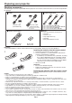
Preparing your projector Checking accessories The following accessories are provided with this projector. Check to be sure that all of the accessories are packed in the package. Cables Power supply part Mini D-SUB 15-pin D-SUB 9-pin Mini D-SUB 15-pin Computer cable (J2552-0072-05) D-SUB 9-pin RS-232C cable (J2552-0114-00) • Used for projector control by computer.
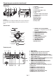
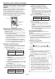
Preparing your projector (continued) Overview 1 2 6 3 4 5 8 13 9 7 10 11 12 Caution: Do not replace the lamp immediately after using the projector because the lamp would be extremely hot and it may cause burns.
Preparing your projector (continued) Bottom side Indicators 1 2 1 3 2 1 Lock bar (SECURITY ANCHOR) • Attach a chain, etc. to this lock bar to anchor the projector. 2 Adjustment feet 1 FILTER indicator 2 STATUS indicator 3 POWER indicator Remote control 1 2 3 4 1 Indicator 2 POWER button (ON/STANDBY) The status is changed between ON and STANDBY.
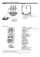
Using the remote control Operational range of the remote control Front of projector About 30° About 30° Rear of projector About 30° About 30° Operate the remote control within a distance of 30 m (98.4 feet) from the projector, pointing the light beam at the remote control photo-sensor (front or rear) of the projector. • Keep the remote control sensor out of direct sunlight or fluorescent lamp light. • Keep the remote control sensor at least 2 m (6 feet) away from fluorescent lamps.
Using the remote control (continued) Setting the ID number of the remote control “COMPLETE” is displayed under the CONTROLLER ID number you entered. • The ID setting dialog box automatically disappears after it is displayed for about 5 seconds. • By pressing any button other than the ID button, number buttons (0 to 9), and ALL button while the ID setting dialog box is being displayed, you can cancel the dialog box.
Setting up your projector Before setting up Before setting up the projector, check the operating environment. If the environmental requirements are not satisfied, the projector may break down or fail. Setup environment The allowable operating temperature varies depending on the HIGH ALTITUDE MODE setting. For use in the STANDARD mode, the allowable operating temperature is +41°F (+5°C) to +104°F (+40°C).
Setting up your projector (continued) Setup adjustment • When the ENTER button is pressed while the LENS SHIFT menu is displayed, the shift mode can be switched between FAST and STEP. When FAST is selected, the lens shifts in a large amount with the p, q, t or u button, and it shifts in a small amount when STEP is selected. • When the ZOOM/FOCUS menu or the LENS SHIFT menu is displayed while no video signal is input to the projector, a crosshatch appears on the entire screen.
Setting up your projector (continued) Setting HIGH ALTITUDE MODE Correcting skewed or distorted image • Set HIGH ALTITUDE MODE in the FEATURE menu according to the altitude at which you use the projector. The default setting is STANDARD. • Select STANDARD when using the projector at an altitude from 0 to 1500 meters. • Select HIGH ALTITUDE when using the projector at an altitude from 1500 to 2700 meters. For the best projection, project images on a flat screen installed at 90 degrees to the floor.
Setting up your projector (continued) Adjustment using the KEYSTONE mode: • When the KEYSTONE-mode adjustment takes effect, the resolution decreases. In addition, stripes may appear or straight lines may bend in images with complicated patterns. They are not due to product malfunctions. • When the KEYSTONE-mode adjustment is performed, the displayed image may be distorted.
Setting up your projector (continued) LOWER RIGHT, LOWER LEFT, UPPER RIGHT, or UPPER LEFT menu You can adjust the horizontal or vertical position of the selected corner. ARC menu You can correct the arc vertically or horizontally focusing on the screen center. Example: Adjustment of the upper left corner position (UPPER LEFT) Press the button. Press the button. Press the button. Press the button. Press the button. Press the button. Press the button. Press the button.
Setting up your projector (continued) Important: • When the CURVED-mode adjustment takes effect, the resolution decreases. In addition, stripes may appear or straight lines may bend in images with complicated patterns. They are not due to product malfunctions. • When the CURVED-mode adjustment is performed, the displayed image may be distorted.
Setting up your projector (continued) Front projection, ceiling mounting Rear projection For ceiling mounting, you need the ceiling mount kit designed for this projector. Ask a specialist for installation. For details, consult your dealer. • The warranty on this projector does not cover any damage caused by use of any non-recommended ceiling mount kit or installation of the ceiling mount kit in an improper location. Ask a specialist for installation. For details, consult your dealer.
Viewing computer images A. Connecting the projector to a computer Preparation: • Make sure that the power of the projector and that of the computer are turned off. • When connecting the projector to a desktop computer, disconnect the computer cable that is connected to the monitor. Computer For analog connection: (For using the COMPUTER/COMPONENT/VIDEO IN 1 terminal.) COMPUTER/ 1.
Viewing computer images (continued) Monitor 1 For monitor connection: 1. Connect the computer cable from the monitor to the MONITOR OUT terminal of the projector. • Only when STANDBY MODE is set to STANDARD, video signal is output from the MONITOR OUT terminal during power standby. MONITOR OUT Computer cable To audio input terminals 1 2 AUDIO OUT For audio output connection: 1. Connect one end of a commercially available audio cable to the AUDIO OUT terminal of the projector. 2.
Viewing computer images (continued) Caution: • Plug in the power cord firmly. When unplugging, hold and pull the power plug, not the power cord. • Do not plug in or out the power cord with your hand wet. It may cause electric shock. • Do not turn on the power before attaching the lens. The cabinet may be exposed to the light from the lamp directly and heated to a high temperature, resulting in deformation.
Viewing computer images (continued) D. Projecting images Preparation: • Remove the lens cap. POWER button (ON/STANDBY) COMPUTER 1, 2 buttons POWER button (ON/STANDBY) p, q, t, u buttons POWER indicator STATUS indicator COMPUTER/DVI-D button DVI-D(HDCP) button p, q, t, u buttons ENTER button ENTER button LENS SHIFT button ZOOM/FOCUS button ZOOM/FOCUS button LENS SHIFT button 1. Confirm the POWER indicator lights up red.
Viewing computer images (continued) 9. Press the ZOOM/FOCUS button to display the ZOOM/FOCUS menu. 10.Adjust with the p or q button to get an approximate size. • When the ENTER button is pressed while the ZOOM/FOCUS menu is displayed, the adjustment mode is switched between FAST and STEP. When FAST is selected, the speed of zoom controlled by the p or q button becomes fast, and it becomes slow when STEP is selected. 11.Press the LENS SHIFT button. The LENS SHIFT menu appears at the center of the screen. 12.
Viewing computer images (continued) Blanking the screen temporarily (BLANK) The video and audio signals are temporarily muted when the BLANK button is pressed. You will hear an operating sound inside the projector. To cancel muting, press the BLANK button again. • You can alter the splash screen optionally. See page 33. • The audio from the AUDIO OUT terminal is also muted by pressing the BLANK button.
Viewing video images A. Connecting the projector to video equipment Preparation: • Make sure that the power of the projector and that of the video equipment are turned off. Connecting to a video player, etc. Video player, or the like BNC cable (option) To video output terminal 1 BNC-RCA connector (option) To VIDEO IN terminal (BNC) To audio output terminals 4 Audio cable (option) To audio input terminals 3 Video player, or the like S-video cable (option) 1 To S-VIDEO IN terminal 1.
Viewing video images (continued) Projector + DVD player or HDTV decoder Some DVD players have an output connector for 3-line fitting (Y, CB, CR). When connecting such DVD player with this projector, use the COMPUTER/COMPONENT/VIDEO IN 2 terminals.
Viewing video images (continued) Connection (for video equipment having a DVI-D terminal) DVI cable (option) COMPUTER/COMPONENT/ VIDEO DVI-D IN (HDCP) To DVI-D terminal AUDIO DVI-D Audio cable (option) Equipment having a DVI-D terminal • • • • To audio output terminals For connection to the DVI-D terminal, use a commercially available DVI cable. Use AUDIO DVI-D terminal for audio input. Some cables may not be connected correctly depending on the size and shape of their connectors.
Viewing video images (continued) D. Projecting images Preparation: • Remove the lens cap. POWER button (ON/STANDBY) POWER button (ON/STANDBY) COMPUTER 1, 2 buttons p, q, t, u buttons POWER indicator STATUS indicator COMPUTER/DVI-D button VIDEO/HDMI button ENTER button LENS SHIFT button ZOOM/FOCUS button ZOOM/FOCUS button HDMI button VIDEO button S-VIDEO button DVI-D(HDCP) button ENTER button p, q, t, u buttons LENS SHIFT button 1. Confirm the POWER indicator lights up red.
Viewing video images (continued) 11.Press the LENS SHIFT button. The LENS SHIFT menu appears at the center of the screen. 12.Press the p or q button to adjust the vertical position and or button to adjust the horizontal position of the displayed image. • When the image is not displayed within the screen, adjust the projection angle. In addition, perform the keystone adjustment, if necessary. (See page 14.) Repeat steps 4, 5 and 9 to 12, if necessary.
Viewing video images (continued) Setting the aspect ratio You can change the aspect ratio of the input video signal (or the ratio of width to height of the image). Change the setting according to the type of the input video signal. How to change the settings: With the remote control: 1. Press the ASPECT button. • Every time the ASPECT button is pressed, the aspect mode changes from NORMAL to 16:9, to FULL, and back to NORMAL.
Menu operation You can make various settings using the displayed menus. Following 6 menus are displayed. IMAGE menu (page 32) INSTALLATION menu (page 33) opt. LAMP MODE SUPER RESOLUTION ON STANDBY MODE LOW PROJECTOR ID 0 AUTO POWER ON OFF PASSWORD FUNCTION 0 AUTO POWER OFF NCM COMPUTER COLOR TEMP. STANDARD ON 0 BACK COLOR 0 IMAGE REVERSE SHARPNESS 0 LENS LOCK SIGNAL menu (page 36) AË HIGH ALTITUDE MODE RESOLUTION (MEMORIZE ) 1024 x 768 INFORMATION LAMP TIME (LOW) 0 VERT.
Menu operation (continued) How to set the menus 1. Press the MENU button. • The menu selection bar is displayed. Selectable menus are displayed by icons. (The menu icon being selected is displayed on a blue background.) opt. IMAGE The name of the menu being selected is displayed. 2. Press the or button to select a menu to use. 3. Press the ENTER button (or button). • The selected menu is displayed. The item being selected is displayed in red letters. opt.
Menu operation (continued) IMAGE menu opt. opt. IMAGE IMAGE COLOR ENHANCER AUTO IRIS OFF 0 NOISE REDUCTION OFF BRIGHTNESS 0 CTI OFF NCM COMPUTER INPUT LEVEL COLOR TEMP. STANDARD CLOSED CAPTION COLOR 0 TINT 0 SHARPNESS ADVANCED MENU COLOR TEMP.
Menu operation (continued) INSTALLATION menu opt. opt. INSTALLATION LAMP MODE LOW ZOOM/FOCUS LOCK AUTO POWER ON OFF LENS SHIFT LOCK AUTO POWER OFF 5min LENS SHIFT RESET SPLASH SCREEN BACK COLOR IMAGE REVERSE LENS LOCK DVI LONG CABLE ITEM LAMP MODE LENS LOCK STANDBY MODE IMAGE CAPTURE ON INSTALLATION STANDARD OFF OFF OK SETUP ON BLUE OFF ENTER AUTO SETTING STANDARD LOW FUNCTION Select this option when you want to view images in a well-lit room.
Menu operation (continued) FEATURE menu opt. opt.
Menu operation (continued) FEATURE menu (continued) ITEM ADVANCED MENU VIDEO SIGNAL SETUP SETTING ENTER AUTO / NTSC / PAL / SECAM / 4.43NTSC / PAL-M / PAL-N / PAL-60 AUTO OFF 3.75% / 7.5% SCART INPUT ON / OFF LAMP WARNING STANDARD SHORT TERM HIDE OSD RESET ALL • • • • • OFF ON OK FUNCTION The ADVANCED MENU is displayed for the following settings. When AUTO is selected, the appropriate video format is automatically selected depending on the input signal.
Menu operation (continued) SIGNAL menu opt. opt. SIGNAL A U H V RRGGBB AUTO RESOLUTION (MEMORIZE ) 1024 x 768 USER RESOLUTION (MEMORIZE) HORIZ. POSITION 0 VERTICAL FREQUENCY HORIZONTAL FREQUENCY VERT. POSITION 0 HORIZ. PIXELS 1024 FINE SYNC. 0 VERT.
Menu operation (continued) NETWORK menu opt. opt. NETWORK NETWORK IP CONFIG PROJECTOR NAME NETWORK CERTIFICATION NETWORK PASSWORD IP CONFIG CONTROL SYSTEM IP ADDRESS 0. 0. 0. 0 ENTER SUBNET MASK 0. 0. 0. 0 DEFAULT GATEWAY 0. 0. 0. 0 NETWORK RESET OK MAC ADDRESS NETWORK RESTART OK SAVE SETTINGS SETTING *****... NETWORK CERTIFICATION ON NETWORK PASSWORD ENTER IP CONFIG DHCP ENTER ON / OFF IP ADDRESS OFF ***.***.***.*** SUBNET MASK ***.***.***.*** DEFAULT GATEWAY ***.***.***.
Menu operation (continued) INFORMATION menu opt. INFORMATION LAMP TIME (LOW) COMPUTER1 INPUT R G B H ITEM LAMP TIME (LOW) SERIAL NUMBER INPUT RESOLUTION VERTICAL FREQUENCY HORIZONTAL FREQUENCY SYNC. TYPE V ****H ********... SERIAL NUMBER RESOLUTION 1024 x 768 VERTICAL FREQUENCY HORIZONTAL FREQUENCY 48.36 kHz SYNC. TYPE 5WIRE 60.00 Hz DESCRIPTION This item shows the lamp operation time calculated based on that the LAMP MODE of LAMP is LOW.
Adjusting projected images To adjust the brightness (CONTRAST and BRIGHTNESS): You can make adjustments for the brightness of the projected image using the menu. (See page 31 for menu setting.) 1. Display the IMAGE menu. 2. Select CONTRAST or BRIGHTNESS by pressing the or button. 3. Adjust the selected item by pressing the or button. To cancel the menu: 4. Press the MENU button. CONTRAST Select to adjust the contrast of the image.
Adjusting projected images (continued) To cancel the menu: 7. Press the MENU button. To enable the stored color temperature: 1. Set COLOR TEMP. to USER in the IMAGE menu. About color temperature Color temperature is a way to show the differences in white. White of which temperature is low appears reddish. When the color temperature rises, white appears bluish. For example, you can change the color temperature using the following procedures.
Adjusting projected images (continued) Adjusting the fineness of the image (SUPER RESOLUTION): You can adjust the fineness of the image using the menu. (See page 31 for menu setting.) With the IMAGE menu: 1. Display the IMAGE menu. 2. Select SUPER RESOLUTION by pressing the or button. 3. Press the or button to select ON . 4. Press the ENTER button. 5. Make adjustment using the or button.
Adjusting projected images (continued) How to adjust the computer image This projector automatically selects a proper signal format according to the type of video signal supplied from the computer. However, video signals from the computer may not be projected correctly depending on the types of the computer and images to be projected. In such a case, make adjustment according to the flowchart below. When the size and position of the computer image are not correct.
Adjusting projected images (continued) How to adjust the image supplied from the computer using the menu: Carry out the following procedures according to the symptoms. Wide strips appear. ��������������� Adjust TRACKING in the SIGNAL menu. The projected image flickers. The projected image is blurred. ��������������������������������������Adjust FINE SYNC. in the SIGNAL menu. The projected image is displaced horizontally. ��������������Adjust HORIZ.POSITION in the SIGNAL menu.
Initial network settings • The display returns the NETWORK menu after selecting OK or CANCEL. • It may take some time to reflect the settings. You can set the network of the projector using the menu. opt. Enabling or disabling the network certification NETWORK PROJECTOR NAME NETWORK CERTIFICATION NETWORK PASSWORD ON You can select whether or not to certify the network communication using the network password. • For details, contact your dealer. (See page 31 for menu setting.) 1.
Initial network settings (continued) IP Settings CLEAR key: ����� Deleting all the entered characters. • You can enter numbers by pressing the number buttons (0 to 9) while holding down the NUM button on the remote control. • The default password is “admin”. 5. Select OK, and NEW NETWORK PASSWORD screen appears if the entered password is correct. • If the entered password is not correct, CURRENT NETWORK PASSWORD screen appears again. (See page 31 for menu setting.) 1. Display the NETWORK menu. 2.
Initial network settings (continued) • You can enter numbers by pressing the number buttons (0 to 9) while holding down the NUM button on the remote control. 5. When selecting OK, the setting is completed as the IP ADDRESS stored temporarily. However, when selecting CANCEL, the setting is completed without storing. • When the setting you entered is correct, the IP CONFIG menu is displayed. If the entered content is not correct, the IP CONFIG menu is displayed after an error dialog is displayed.
Initial network settings (continued) Initialization of Network Settings Glossary For more detail of the glossary below, refer to the technical book that is commercially available. (See page 31 for menu setting.) 1. Display the NETWORK menu. 2. Press the or button to select NETWORK RESET. NETWORK RESET OK 3. Press the ENTER button. • Confirmation dialog appears. 4. Press the ENTER button again, and the Network Settings can be initialized (except for IP CONFIG).
Advanced features Changing the image displayed at the startup • The image within the outer edges of the red frame is captured. • The captured image is displayed in the REAL mode automatically. You can display your desired image as the startup screen (or splash screen). By setting the menu, you can use such image instead of the background image that is displayed when no video signal is supplied.
Advanced features (continued) Password function This projector is equipped with the password function that is designed for prevention of wrong operation by children and restriction on operation by other than specified users. The password function has 3 modes as follows. DISPLAY INPUT........... When the projector is turned on, the startup screen (or splash screen) will appear and stay on the screen until the password is entered.
Advanced features (continued) Picture in Picture (PinP) Magnifying the displayed image One of the special features of this projector is the picture-in-picture (PinP) mode. The PinP mode allows you to view the images from different sources at the same time. • While viewing the image from the COMPUTER1, COMPUTER2, DVI, or HDMI input source, you can display the image from the VIDEO or S-VIDEO input source as a sub image.
Advanced features (continued) Supervising and controlling by computer Important: • When you set CONTROL SYSTEM to CRESTRON in the NETWORK menu, the web control for Crestron is enabled. For such control, Adobe Flash Player should be installed in advance. You can download Adobe Flash Player from the website of Adobe Systems Incorporated. • When you set CONTROL SYSTEM to CRESTRON in the NETWORK menu, you cannot use the control by ProjectorView Global+, which is the software supplied with the projector.
Advanced features (continued) Connection For details of the connection, see “LAN control UTILITY operation manual” in the CD-ROM. When STANDBY MODE of the INSTALLATION menu of the projector is set to LOW, the network function is disabled. To enable the network function, set STANDBY MODE to STANDARD or LAN. (See page 33.) Configure the initial network settings first. You can configure the initial settings using the projector menu (see pages 44 to 47) or ProjectorView Global+ or ProjectorView.
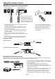
Replacing the lamp Caution: • Don’t remove the lamp for any purpose other than replacement. Unnecessary removal of the lamp may result in a breakdown. • This projector uses a high-pressure mercury lamp as the light source. The high-pressure mercury lamp may explode or fail to illuminate permanently because of an impact, scratch, or deterioration through use. The period of time until explosion or permanent failure to illuminate varies considerably from lamp to lamp, depending on operation conditions.
Replacing the lamp (continued) To replace the lamp: 7. Insert the lamp cover (b) into the projector and tighten two screws (a) on the lamp cover firmly using a Phillips screwdriver. 1. Unplug the power cord from the outlet or appliance inlet. 2. Loosen two screws (a) that are securing the lamp cover using a Phillips screwdriver and remove the lamp cover (b) from the projector. (b) (b) (a) • You cannot turn on the projector without attaching the lamp cover.
Replacing the lamp (continued) When removing the lamp from the ceiling-mounted projector When removing the lamp from the ceiling-mounted projector, use the lamp replacement tray packed with the projector or option lamp to prevent glass fragments from scattering. • Assemble the lamp replacement tray according to the procedure shown on it. 1. Follow steps 1 to 3 on page 54. 2. Attach the lamp replacement tray to the projector as shown in the figure. 3.
Maintenance Warning: • Do not use flammable solvents (benzene, thinner, etc.) and flammable aerosols when cleaning the projector body and lens. Flammable substances may ignite causing fire or breakdown while the lamp is illuminating. Cleaning of the filter Caution: • Be sure to turn off the lamp and unplug the power cord from the wall outlet before you perform any maintenance on the projector. • Ask your dealer for annual cleaning of the inside of the projector.
Replacing the lens Mounting the lens (option lens) You can replace the lens on this projector. The lens can be replaced with the separately sold option lens according to the usage environment of the projector. For details of the specification of the option lens, contact your local dealer. • Before you replace the lens, be sure to turn off the projector and unplug the power cord from the wall outlet.
Troubleshooting Before asking for repair of the projector, check the following. If the symptom persists, stop using the projector, be sure to unplug the power plug, and then contact your dealer. No image appears on the screen. Problem Solution Power can not be turned on. • Check whether the indicators are on or off and how they are lightning.
Troubleshooting (continued) No image appears on the screen. (continued) Problem Solution The screen for entering the password appears. • PASSWORD FUNCTION in the FEATURE menu has been set to DISPLAY INPUT enable the password lock. Enter the password or contact the person in charge of management of the projector. (See page 49.) “NO SIGNAL” is displayed. • Turn on the power of the connected device, or check whether there is something wrong with the connected device.
Troubleshooting (continued) Images are not displayed correctly. (continued) Problem Solution Hue is not appropriate. Tint in projected images is incorrect. Different color tint. • • • • Only the motion areas in the images supplied from the computer aren’t displayed. Projected images are obscured. Noise appears around the image. Check that the cables connected to the external devices are not broken. Check that COMPUTER INPUT in the SIGNAL menu is correctly set. (See page 36.
Troubleshooting (continued) Problem Solution FOCUS/ZOOM doesn’t work. Lens shift doesn’t work. • Check that LENS LOCK in the INSTALLATION menu isn’t ON. (See page 33.) If the following problem occurs after the lamp is replaced, check the following first. Problem Solution The projector does not turn on. • Fit the lamp cover securely. (See page 54.) • Reset the lamp operating time. (See page 54.) The STATUS indicator illuminates red. • Reset the lamp operating time. (See page 54.
Indicators This projector has 3 indicators, each of which shows the operation condition of the projector. The following offer solutions to possible problems. If these problems persist, turn the projector off and consult your dealer.
Specifications The specifications and outside appearance of the projector are subject to change without prior notice.
Specifications (continued) Specification of RGB signals in each computer mode of the projector Signal mode TV60, 480i (525i) TV50, 576i (625i) 1080i60 (1125i60) 1080i50 (1125i50) 480p (525p) 576p (625p) 720p60 (750p60) 720p50 (750p50) 1080p60 (1125p60) 1080p50 (1125p50) CGA70 CGA84 CGA85 VGA60 VGA72 VGA75 VGA85 SVGA56 SVGA60 SVGA72 SVGA75 SVGA85 SVGA95 XGA60 XGA70 XGA75 XGA85 SXGA70a SXGA75a SXGA85a WXGA60 WXGA60a WXGA60b WXGA60c WXGA+60 WXGA++60 SXGA60b SXGA75b SXGA85b SXGA60 SXGA75 SXGA85 SXGA+60 SXGA+75
Specifications (continued) Specification of RGB signals in each computer mode of the projector (continued) • TV60 and TV50 are equivalent to 480i and 576i respectively. When these signals are supplied to the VIDEO IN or S-VIDEO IN terminal, the signal mode is indicated as TV60 or TV50. When they are supplied to the COMPUTER/COMPONENT VIDEO IN terminals, the signal mode is indicated as 480i or 576i.
Specifications (continued) Specification of the attached lens With short throw zoom lens (OL-XL7100SZ) F2.0 - F2.6 f = 19.3 - 24.9 mm Electrical drive (zoom ratio 1.3 : 1) 40 inch (81 cm X 61 cm) - 300 inch (610 cm X 457 cm) Shortest (Wide) Longest (Tele) Standard (H0) H1 H2 inch cm inch cm inch cm inch m inch m inch cm inch cm inch cm inch cm 40 102 32 81 24 61 37 0.9 48 1.2 -12 -30 14 37 14 37 10 24 60 152 48 122 36 91 56 1.4 73 1.
Specifications (continued) With rear projection short throw (OL-XL7100FR) F2.2 f = 12.9 mm Electrical drive 40 inch (81 cm X 61 cm) - 200 inch (406 cm X 305 cm) Width (W) Height (H) inch 40 cm 102 inch 32 cm 81 inch 24 60 152 48 122 80 203 64 163 100 254 80 120 305 96 150 381 200 508 Projection distance (L) Standard (H0) cm 61 inch 24 m 0.6 inch -12 cm -30 36 91 37 0.9 -18 -46 48 122 50 1.3 -24 -61 203 60 152 63 1.6 -30 -76 244 72 183 76 1.
MITSUBISHI ELECTRIC CORPORATION 1 Zusho Baba, Nagaokakyo-City, Kyoto Japan U-A