
- Mitsumi Electronics Welding System User Manual


PARAMETERS
123
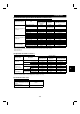
(4) I/O signals
Signal Terminal Used Function Description Remarks
X14
Depending on
Pr. 180 to Pr. 186
PID control
selection
Switch on X14 to select PID control.
Set any of "10, 11, 20
and 21" in Pr. 128.
2 2 Set point input Enter the set point for PID control. Pr. 128 = 20, 21
11
Deviation signal
input
Enter the deviation signal calculated externally. Pr. 128 = 10, 11
Input
44
Process value
input
Enter the 4-20mADC process value signal from
the detector.
Pr. 128 = 20, 21
FUP Upper limit output
Output to indicate that the process value signal
exceeded the upper limit value.
FDN Lower limit output
Output to indicate that the process value signal
exceeded the lower limit value.
(Pr. 128 = 20, 21)
RL
Depending on
Pr. 191 to Pr. 195
Forward (reverse)
rotation direction
output
"Hi" is output to indicate that the output
indication of the parameter unit is forward
rotation (FWD) or "Low" to indicate that it is
reverse rotation (REV) or stop (STOP).
(Pr. 128 = 10, 11,
20, 21)
Open collector output
Output
SE SE
Output terminal
common
Common to terminals FUP, FDN and RL
#
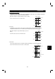
To start PID control or Advanced PID control, switch on the X14 signal. When this signal is off, ordinary
inverter operation is performed without the PID action being done.
#
Enter the set point across inverter terminals 2-5 or into Pr. 133 and enter the process value signal across
inverter terminals 4-5. At this time, set "20" or "21" in Pr. 128.
#
When entering an externally calculated deviation signal, enter it across terminals 1-5. At this time, set "10"
or "11" in Pr. 128.
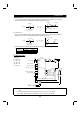
Item Entry Description
Set 0V as 0% and 5V as 100%.
When "1, 3, 5, 11, 13 or 15" is set in Pr. 73
(5V selected for terminal 2).
Across terminals 2-5
Set 0V as 0% and 10V as 100%.
When "0, 2, 4, 10, 12 or 14" is set in Pr. 73
(10V selected for terminal 2).
Set point
Pr. 133 Set the set point (%) in Pr. 133.
Set
−
5V as
−
100%, 0V as 0% and
+
5V as
+
100%.
When "2, 3, 5, 12, 13 or 15" is set in Pr. 73
(5V selected for terminal 1).
Deviation
signal
Across terminals 1-5
Set
−
10V as
−
100%, 0V as 0% and
+
10V as
+
100%.
When "0, 1, 4, 10, 11 or 14" is set in Pr. 73
(10V selected for terminal 1).
Process
value
Across terminals 4-5 4mADC is equivalent to 0% and 20mADC to 100%.
4