Index Important Information ................................................................................................................................... Safety Precautions, Maintenance & Recommended Use ............................................................................ Contents ....................................................................................................................................................... Parts Name and Functions .......................................
Important Information DECLARATION OF CONFORMITY This device complies with Part 15 of FCC Rules. Operation is subject to the following two conditions. (1) This device may not cause harmful interference, and (2) this device must accept any interference received, including interference that may cause undesired operation. U.S. Responsible Party: Address: Tel. No.: Mitsubishi Digital Electronics America, Inc. 9351 Jeronimo Road, Irvine, California 92618 U.S.A.
English Important Information WARNING TO PREVENT FIRE OR SHOCK HAZARDS, DO NOT EXPOSE THIS UNIT TO RAIN OR MOISTURE. ALSO, DO NOT USE THIS UNIT’S POLARIZED PLUG WITH AN EXTENSION CORD RECEPTACLE OR OTHER OUTLETS UNLESS THE PRONGS CAN BE FULLY INSERTED. REFRAIN FROM OPENING THE CABINET AS THERE ARE HIGH VOLTAGE COMPONENTS INSIDE. REFER SERVICING TO QUALIFIED SERVICE PERSONNEL. CAUTION CAUTION TO REDUCE THE RISK OF ELECTRIC SHOCK, MAKE SURE POWER CORD IS UNPLUGGED FROM WALL SOCKET.
Safety Precautions, Maintenance & Recommended Use FOR OPTIMUM PERFORMANCE, PLEASE NOTE detaching the system from the power supply. The monitor THE FOLLOWING WHEN SETTING UP AND USING should be installed close to a power outlet, which is easily THE LDT371V LCD COLOR MONITOR: accessible. • • Handle with care when transporting. Save packaging for DO NOT OPEN THE MONITOR. There are no user transporting.
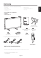
Contents • LCD monitor • Main switch cover • Power Cord (3m) • Screw for Main Switch cover x 2 • Video Signal Cable (4m) • Cable folder • User’s Manual • Wireless Remote Control and AAA Batteries • Clamper x 2 • Screw for Clamper x 2 User’s Manual Video Signal Cable (D-SUB to D-SUB Cable) Screw for Main switch cover (M3 x 10) x 2 Main switch cover Cable Folder Screw for Clamper (M4 x 8) x 2 Clamper x 2 * The supplied power cord varies depending on destination.
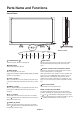
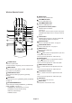
Parts Name and Functions Control Panel 9 10 OFF ON Button Location EXIT 8 1 POWER button ( 7 6 5 MUTE 3 2 4 ) 8 Switches the power on/off. See also page 18. 2 INPUT 1 EXIT button Activates the OSD menu when the OSD menu is turned-off. Acts as EXIT button to move to previous menu with OSD menu. MUTE button Switches the audio mute ON/OFF. 9 3 INPUT button Acts as SET button with OSD menu. (Toggle switches between [RGB1], [RGB2], [RGB3], [DVD/HD], [VIDEO] and [VIDEO] .
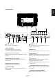
English Terminal Panel 1 AC IN connector 7 Connects with the supplied power cord. To input audio signal from external equipment such as a AUDIO IN 1, 2, 3 computer, VCR or DVD player. 2 RGB 1 IN (DVI-D) To input digital RGB signals from a computer. 8 * This connector does not support analog input. 3 AUDIO OUT To output the audio signal from the AUDIO IN 1,2 and 3 jack.
Wireless Remote Control 6 MUTE button To switch the mute function on/off. 7 VOLUME UP button Increase the audio output level. 8 VOLUME DOWN button Decrease the audio output level. 9 PIP (Picture In Picture) button ON/OFF button: PIP-ON/OFF. See page 23. INPUT button: Select the ‘picture in picture’ input signal. CHANGE button: Replaces to the main picture and sub picture. 10 STILL button ON/OFF button: To switch the still picture mode on/off. CAPTURE button: Updates the still picture.
Handling the remote control Point the top of the remote control toward the LCD monitor's * Do not subject to strong shock. remote sensor during button operation. Use the remote control within a distance of about 7 m/23 ft. from the front of the LCD monitor's remote control sensor and at a horizontal and vertical angle of within 30° within a distance of * Do not allow water or other liquid to splash the remote control. If the remote control gets wet, wipe it dry immediately.
Setup Procedure 1. Determine the installation location CAUTION: DO NOT ATTEMPT TO INSTALL THE LCD MONITOR BY YOURSELF. 3.Connect external equipment (See page 13-17) • Installing your LCD display must be done by a qualified To protect the connected equipment, turn off the main power before making connections. technician. Contact your dealer for more information. CAUTION: MOVING OR INSTALLING THE LCD MONITOR MUST BE DONE BY TWO OR MORE PEOPLE. • Refer to your equipment user manual.
12. To prevent the main power switch from being changed To prevent the ability to use the main power switch, please attach the main switch, which is enclosed as an accessory. NOTE: With the main power switch cover in place, the main power switch can not be turned off. Remove main 11. Installing and removing stand power switch cover in order to switch off the display. How to install stand 1. Please turn monitor off. 2.
How to Mount and Attach Options to the LCD Monitor You can attach mounting accessories to the LCD monitor in one of the following two ways: 1. In the upright position 3. Ventilation Requirements for enclosure mounting To allow heat to disperse, leave space between surrounding objects as shown in the diagram below. 2. Lay the screen face down 4.
Connections * First turn off the power of all the attached equipment and make connections. * Refer to the user manual included with each separate piece of equipment.
Connecting a Personal Computer Connecting your computer to your LCD monitor will enable you to display your computer's screen image. Some video cards may not display an image correctly. Connect the LCD Monitor to a Personal Computer • To connect the RGB 2 IN connector (mini D-sub 15 pin) on the LCD monitor, use the supplied PC - Video RGB signal cable (mini D-sub 15 pin to mini D-sub 15 pin).
Connections can be made with equipment that is equipped with a digital interface compliant with the DVI (Digital Visual Interface) standard. Connect the LCD Monitor to a Computer with a Digital Output • The RGB 1 IN connector also accepts a DVI-D cable. • Input TMDS signals conforming to DVI standards. • To maintain display quality, use a cable with a quality prescribed by DVI standards. • The AUDIO IN 1, 2 and 3 can be used for audio input.
Connecting a DVD Player with component out Connecting your DVD player to your LCD monitor will enable you to display DVD video. Refer to your DVD player owner’s manual for more information. Connect the LCD Monitor to a DVD Player • To connect the DVD/HD In connector (BNC) on the LCD monitor, use a separately available BNC connector cable. You will need a BNC-to-RCA adapter to connect a DVD player with an RCA pin jack to the BNC connector cable (not provided).
You can connect your stereo amplifier to your LCD monitor. Refer to your amplifier owner's manual for more information. Connect the LCD Monitor to a Stereo Amplifier • Turn on the LCD monitor and the amplifier only after all connections have been made. • Use an RCA cable to connect the AUDIO OUT connector (RCA) on the LCD monitor and the audio input on the amplifier. • Do not reverse the audio left and right jacks. • The AUDIO IN 2 and 3 (both RCA) can be used for audio input.
Basic Operation Power ON and OFF Modes The LCD monitor power indicator will turn green while powered on or red in off mode. The monitor can be powered on or off using the following three options: 1. Pressing the Main Power Switch. NOTE: When the Main Power Switch is used to power off the LCD monitor, the remote control and the power button will not activate the on mode and both green and red power indicator turn off. Be sure to turn the Main Power Switch to the on mode before using these two options.
NORMAL: Display by the inputed signal aspect ratio by PC signal, or display in 4:3 aspect ratio at DVD/HD or VIDEO signal. FULL: Display in entire screen. DYNAMIC: Expand 4:3 pictures to the entire screen with non-linearity. (Some around image will be cut by expansion.) CUSTOM (ZOOM) Image can be expanded beyond the active display area. The image which is outside of active diaplay area is not displayed.
OSD (On-Screen-Display) Controls Press MENU button to open Main menu. Press UP or DOWN button to select sub-menu. Press SET button to decide. Press UP or DOWN, and PLUS or MINUS button to select function, or control which you like. Press SET button to decide. Press MENU or EXIT button to exit. Remote Control SET Press UP or DOWN button to select. Press INPUT button to decide Press UP or DOWN, and PLUS or MINUS button to select function, or control which you like.
TINT *:INPUT DVD/HD, VIDEO only Adjust the color of the screen. COLOR Press + button to increase color depth. Press - button to decrease color depth. *:INPUT DVD/HD, VIDEO only R, G, B: Increases or decreases Red,Green, and Blue depending upon which is selected. The change in color will appear on screen and the direction (increase or decrease) will be shown by the color bars. NOTE: It can be adjusted only when USER is selected by COLOR TEMPERATURE.
ZOOM MODE You can select “FULL”, “NORMAL” and “CUSTOM”. (INPUT RGB1/2/3 only) You can also select “FULL”, “NORMAL” “DYNAMIC” and “CUSTOM”. (INPUT DVD/HD, VIDEO only) Selecting “DYNAMIC” will make the screen display panoramic with the expansion of the middle and outside of the screen changed. (The upper and the bottom of the image will be cut by expansion.) Dynamic image is the same as FULL size image when HDTV signal is input.
English Main-Menu PIP(PICTURE IN PICTURE) Sub-Menu Selecting the size of picture inserted at the "Picture-in-Picture" (PIP) mode. "Large", "Middle" and "Small" are available. PIP SIZE Selecting the sound source in PIP mode. When selecting "MAIN AUDIO", you will get the sound for the main picture and when selecting "PIP AUDIO", you will get the sound for the picture instead. PIP AUDIO Selecting PIP Reset allows you to reset all OSD settings from PIP setting.
Select "SCREEN SAVER" functions to reduce the risk of the "image persistence". GAMMA: The display gamma is changed and fixed when selected "ON". COOLING FAN: The built in cooling fan is always on when set "ON". BRIGHTNESS: The brightness is decreased when selected "ON". MOTION: Image is slightly expanded and moves 4 directions (UP, DOWN, RIGHT, LEFT) periodically (Need setting the time for movement).
English Main-Menu CONFIGURATION 2 Sub-Menu The OSD control menu will stay on as long as it is use. In the OSD Turn Off submenu, you can select how long the monitor waits after the last touch of a button to shut off the OSD control menu. The preset choices are 5 -120 seconds. OSD TURN OFF Selects the information OSD display or not. The information OSD will display when input signal or source change or warning message like as no-signal or out-of range. A time between 1 to 10 seconds is available.
Main-Menu ADVANCED OPTION Sub-Menu Selects to decision of input signal about below timings, 1024x768, 1280x768 and 1360x768. AUTO: Determines the resolution automatically. 1024x768: Determines the resolution as 1024x768 1280x768: Determines the resolution as 1280x768 1360x768: Determines the resolution as 1360x768 INPUT RESOLUTION *:INPUT RGB2/3 only Selects a level of black expansion. In case of go under the black cut-off level, please adjust the "Black level" in moderation on OSD menu.
HEAT STATUS Adjusts the delay time from "standby" to "power on" mode. "POWER ON DELAY" time is selectable between 0 and 50 sec. POWER ON DELAY Adjusts the current date and time for internal clock. You should set this function when you use "SCHEDULE". DATE AND TIME Programs the monitor's working schedule. Schedule the power on and power off with hour and a day of the week. Also sets the input port. This OSD can't remove except EXIT.
< Recommendations > For preventing the fast transition to Image Sticking, and for longer life usage of LCD, following are recommended. 1. Fixed image should not be displayed for long period, and changed to another images with short cycle. 2. When no use, please turn off the monitor by remote control, or use Power Management Function of monitor or use Schedule Function of monitor. 3. Reducing the environmental temperature is effective for long life use.
Controlling the LCD monitor via RS-232C Remote Control English This LCD monitor can be controlled by connecting a personal computer with a RS-232 terminal. Functions that can be controlled by a personal computer are: • Power ON or OFF • Switching between input signals Connection LCD Monitor + PC PC RS-232C Cable NOTE: If your PC (IBM or IBM compatible) is equipped only with a 25-pin serial port connector, a 25-pin serial port adapter is required. Contact your dealer for details.
3) Control sequence (1) The command from a computer to the LCD monitor will be sent in 600ms. (2) The LCD monitor will send a return command 600ms* after it has received and encoded. If the command isn’t received correctly, the LCD monitor will not send the return command. (3) The personal computer checks the command and confirms if the command, which has been sent, has been executed or not. (4) This LCD monitor sends various codes other than return code.
Reduced Footprint: Provides the ideal solution for environments requiring superior image quality but with size and weight limitations. The monitor’s small footprint and low weight allow it to be moved or transported easily from one location to another. Color Control Systems: Allows you to adjust the colors on your screen and customize the color accuracy of your monitor to a variety of standards.
Troubleshooting No picture • The signal cable should be completely connected to the display card/computer. • The display card should be completely seated in its slot. • Front Power Switch and computer power switch should be in the ON position. • Check to make sure that a supported mode has been selected on the display card or system being used. (Please consult display card or system manual to change graphics mode.
Specifications Product Specifications LCD Module Frequency Diagonal: Pixel Pitch: Resolution: Color: Brightness: Contrast Ratio: Response time: View Angle: Design View Distance: Horizontal: Vertical: Pixel Clock Viewable Size Input Signal PC-Input: Analog Input 37"/94.0cm 0.600mm 1366 x 768 dots Over 16 million colors (depending on video card used) 500cd/m2 (typ.) 1200:1 (typ.) 12ms (typ.) Up 88°/Down 88°/Left 88°/Right 88°(typ.) @CR>10 1000mm/39.4inches 15.625/15.734kHz, 31.5kHz - 91.1kHz 50.0/58.
Pin Assignment 1) Analog RGB input (MiniDsub15p): R G B 2 Pin No Name 1 Video Signal Red 2 Video Signal Green 3 Video Signal Blue 4 GND 5 DDC-GND 6 Red-GND 7 Green-GND 8 Blue-GND Mini D-SUB 15P 1 9 +5V (DDC) 10 SYNC-GND 11 GND 12 DDC-SDA 13 H-SYNC 14 V-SYNC 15 DDC-SCL 5 6 10 11 15 2) S-VIDEO input: V I D E O Pin No Name 1 GND 2 GND 3 Y (Luminance) 4 C (Chroma) 3) Digital RGB input (DVI-D): R G B 1 Pin - Assignment of DVI connector: 1 TX2- 9 TX1- 17 TX0- 8
MITSUBISHI Contact Information North America Europe MESCA (Mitsubishi Electric Sales Canada Inc.) http://www.mitsubishielectric.ca Information Technologies Group, 4299 14th Avenue, Markham, Ontario L3R 0J2, Canada Sales Phone :+1-(905) 475-7728 Fax :+1-(905) 475-7958 E-mail :projectors@mitsubishielectric.ca Technical Phone :+1-(905) 475-7728 Fax :+1-(905) 475-7958 Customer Care E-mail :support@mitsubishielectric.ca MEU-FRA (Mitsubishi Electric Europe B.