No.99MBC032A3 SERIES No.544 LSM-9506 Laser Scan Micrometer User's Manual Read this User’s Manual thoroughly before operating the instrument. After reading, retain it close at hand for future reference.
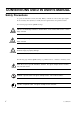
CONVENTIONS USED IN USER'S MANUAL Safety Precautions To operate the instrument correctly and safely, Mitutoyo manuals use various safety signs (Signal Words and Safety Alert Symbols) to identify and warn against hazards and potential accidents. The following signs indicate general warnings: DANGER WARNING Indicates an imminently hazardous situation which, if not avoided, will result in serious injury or death.
CONVENTIONS USED IN USER'S MANUAL On Various Types of Notes The following types of notes are provided to help the operator obtain reliable measurement data through correct instrument operation. IMPORTANT • An important note is a type of note that provides information essential to the completion of a task. You cannot disregard this note to complete the task. • An important note is a type of precaution, which if neglected could result in a loss of data, decreased accuracy or instrument malfunction/failure.
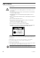
PRECAUTIONS 1. Safety Precautions The Mitutoyo Laser Scan Micrometer LSM-9506 uses a laser beam. CAUTION 1) “This LSM conforms to the US CDRH regulations in 21 CFR 1040 for a class II laser product.” 2) Do not look directly into the laser beam. (Never look into the emission window, even when no light is emitted.) 3) Do not observe the laser beam directly through optical equipment, such as a magnifying lens. 4) When measuring flat objects with mirror finishes, avoid looking at the reflection on the surface.
SAFETY PRECAUTION LABELS LOCATED ON LSM-9506 CAUTION-Laser Light when open DO NOT STARE INTO BEAM CAUTION-Laser Light when open DO NOT STARE INTO BEAM AVOID EXPOSURE-LASER RADIATION IS EMITTED FROM THIS APERTURE Beam attenuator CAUTION LASER LIGHT-DO NOT STARE INTO BEAM LASER EMISSION INDICATOR LASER EMISSION CAUTION-Laser Light when open DO NOT STARE INTO BEAM Complies_with_21_CFR_1040.
INSTALLING CONDITIONS The Mitutoyo Laser Scan Micrometer LSM-9506 is both a precision optical instrument and a precision electric instrument, and it is designed for indoor use. Therefore, it must be carefully installed and the following conditions must be taken into consideration to attain the highest possible accuracy. 1. Vibration Install this unit if possible in a place where it will not be subject to vibration.
CONTENTS CONVENTIONS USED IN USER'S MANUAL ................................................................. i NOTES FOR EXPORTING ...............................................................................................ii PRECAUTIONS ...............................................................................................................iii SAFETY PRECAUTION LABELS LOCATED ON LSM-9506 ........................................iv INSTALLING CONDITIONS ..............................................
3.2.14 Group judgment .............................................................................. 3.2.15 Recording the amount of light ........................................................ 3.3 Outline of the Display Contents .................................................................. 3.3.1 Display unit ..................................................................................... 3.3.2 Data display unit ............................................................................. 3.
4.2 4.3 4.4 4.5 5. No. 99MBC032A b. Setting the RS-232C communication baud rate (Guidance: BAUD) ........................................................... c. Setting the RS-232C communication data bits (Guidance: LENGTH) ...................................................... d. Setting the RS-232C communication parity bit (Guidance: PARITY) ........................................................ e. Setting the delimiter for communication (Guidance: DELIMT) ............................................
6. INTERFACE UNIT ................................................................................................ 6-1 6.1 RS-232C Interface ........................................................................................ 6-1 6.1.1 Specifications .................................................................................... 6-1 6.1.2 Connections ...................................................................................... 6-3 6.1.3 Printer interface ..................................
1 1.1 INTRODUCTION This chapter describes the Laser Scan Micrometer (LSM) models and nomenclature of the Display unit and the Measuring unit. Outline This system is an accurate, non-contact measurement system capable of measuring workpiece dimensions at a high speed using a highly directional scanning laser beam. This non-contact optical measuring system is capable of measuring workpieces which are difficult to measure with conventional measuring instruments.
1.3 Nomenclature This section gives the name of each part in the LSM system. 1.3.1 (1) Display Unit Front panel Workpiece Position indicator LED Operation keys Data display Mitutoyo LASER SCAN MICROMETER LSM-9506 SHIFT RUN C.RUN S.PR PRINT SET READ 7 8 9 C H.CAL 4 5 6 LIMIT PROG. LOCK CAL OFFSET S.E DUAL LASER EMISSION –NG GO +NG RUN L.CAL 1 2 3 MASTER OFFSET 0 • +/- REF STAT S.E ENT BUSY LOCK A.CL UNIT M.
1. INTRODUCTION (3) Rear panel AC power inlet Fuse holder Serial number label GND terminal Scanning signal connector Digimatic output connector Foot switch RS-232C connector Remote interlock connector TIP The terminal located at the left end of the power input terminal and marked (by a symbol or ) is the grounding terminal to keep the potential of signal line of this unit equal with other instrument connected. It is used to enhance resistance against electrical interference. 1.3.
MEMO 1-4 No.
2 2.1 SETUP This chapter describes the connection between the Display Unit and Measuring Unit. Unpacking and Acceptance Check Your LSM has been thoroughly inspected prior to shipment. The mechanical, electrical, and optical systems are guaranteed to operate properly. Unpack the package and check that the main unit is not damaged, and all the accessories listed are present. Contact Mitutoyo if anything is damaged or missing. 2.
Step 2: Checking the remote interlock connector Make sure that the short-circuiting pin is inserted into the “REMOTE INTERLOCK” connector on the rear panel of the Display Unit. If this short-circuiting pin is not inserted, laser emission is disabled, even if the power switch is on. To emergency stop laser emission, refer to the following diagram.
2. SETUP 2.3 Preliminary Checks The necessary connections should be completed by following the procedure described in the previous chapter. Simplified operation checks are described here. Step 1: Fully open the lens cap and shutter of the Measuring Unit. Fully open the lens caps and beam shutters of both the emission unit and reception unit to ready the laser beam for emission. The lens caps should be completely removed, and the shutters should be as shown in the diagram below.
• An error may be displayed at this stage, PROG however, the display at the right is not actually an error. Check the shutter of the Measuring Unit. For information about other errors that may result refer to Section 7.3, “Error Messages and Remedies”. 2-4 No.
2. SETUP 2.4 Initializing the LSM-9506 After making sure that this unit is operating normally, initialize the LSM-9506. The initialization procedure is as follows: Step 1: Turn off the power. Step 2: Turn on the power while holding down the C key. Hold down the C key for approximately 2 seconds, even after the power is on. Step 3: When the self check has been completed, the PROG display shown at the right will appear. To initialize, press the ENT key.
MEMO 2-6 No.
3 DISPLAYS AND KEY OPERATIONS This Display Unit is provided with many useful functions that can be customized according to the user's needs. This chapter describes these functions and key operations. 3.1 Outline of the Operation Modes 3.1.1 Outline of the Operation Modes In order for the user to understand the measurement principle of the LSM, the following paragraphs describe about the system block diagram, segments (measurement positions) and measurement interval (measurement time). 3.1.1.
The configuration of the system is shown in the block diagram described in the previous page. A laser beam emitted from the laser oscillator is directed at the polygon mirror which rotates at high speed and is synchronized by clock pulses. The laser beam that is reflected by the polygon mirror is then collimated by the collimator lens towards the workpiece.
3. DISPLAYS AND KEY OPERATIONS 3.1.1.2 Setting the segment Set the objective portion of a workpiece to be measured. The highlighted and shaded portions created when the laser scans over the workpiece are controlled with each assigned number. In the basic setup a selection must be made from one of two cases: case where there are 1 to 4 highlighted and shaded sections, and case where there are 1 to 127 similar sections.
3.1.1.3 Measurement interval (measurement time) A measurement interval (measurement time) varies depending on the averaging method and the number of scans selected for the measurement data. There are two types of averaging method: the arithmetical average and the moving average. Select the one best suited for the user’s purpose.
3. DISPLAYS AND KEY OPERATIONS 3.1.2 Outline of the Operation Modes The LSM system has the following modes: 1: Basic setup mode, 2: Calibration mode, 3: Function setup mode, 4: Other setup mode, 5: Statistical result display mode, and 6: Measurement mode. Power ON Error check Power ON + SET SET 1 : Basic setup mode 6 : Measurement mode LOCK UNIT , LOCK UNIT SHIFT H.CAL Ready state , L.CAL 4: Other setup mode 2 : Calibration mode RUN ENT SHIFT ( LOCK UNIT ) C.
3.1.2.1 Basic setup mode • This mode is used to customize the basic setup conditions, including the resolution, interface conditions, and available functions, according to the measurement requirements. For more information, refer to Section 4.1, “Basic Setup”. • To enter the basic setup mode turn on the power (turn the key switch clockwise from the “O” position to the “I” position) while holding down the SET key. Hold down the SET key for about 2 seconds to initiate the basic setup mode. 3.1.2.
3. DISPLAYS AND KEY OPERATIONS 3.1.2.6 Measurement mode This mode can be divided into the following operational states: 1) Measurement in the ready state • This is the measurement mode that is entered immediately after the power is turned on or if another measurement mode is aborted by pressing the C key (or by the “CL” command from the RS-232C interface).
5) Sample measurement • A measurement where the number of samples is set to “2~999” is called a “sample measurement”. • In practice this will take place as a single-run measurement or a continuous-run measurement. From the measured data the calculation items (mean, maximum value, minimum value, and range) that have been set for the sample measurement will be calculated and the resulting data will be automatically subject to GO/NG judgment.
3. DISPLAYS AND KEY OPERATIONS 3.2 Techniques and Terminology of Setup Functions 3.2.1 Program • A measurement will automatically be performed according to the registered (programmed) contents including the segment (feature to be measured) and GO/NG judgment criteria, etc., in advance. Registration is performed in the function setup mode. • This unit can hold a maximum of 10 programs, which may include various settings suitable for up to ten kinds of workpieces.
3.2.3 Function setup • Use this procedure to set up the conditions necessary for measurement. For each program number register measurement conditions including the segment (part feature to be measured), measurement interval (measurement time), and GO/NG judgment criteria that are the best suited for the objective workpiece. • To enter the function setup mode press the SET key in the ready state.
3. DISPLAYS AND KEY OPERATIONS b) Plate (Sheet) • If the workpiece being measured is a transparent plate (sheet) with edges that are not chamfered or beveled, there may not be a sharp contrast in the amount of light at the transition from the highlighted portion to the shaded portion. As a result, the voltage generated by the incident light on the photo-electric element can not reach the threshold voltage level (SHL), and Segment 2 is determined to not exist (Err-0).
3. Change the SHL Change the standard SHL (50%) of the photo-electric signal generated. The SHL can be changed in a range between 50% and 90%. First place a reference workpiece in the measuring region and connect the oscilloscope probe to the SCAN SIG connector located on the rear panel of the Main Unit. Observe the signals. Set the SHL to the center of the waveform that corresponds to the shadow from the smaller edge.
3. DISPLAYS AND KEY OPERATIONS 3.2.6 Automatic measurement with an edge specification • If the edge specification is made, it is possible to automatically measure IC or connector leads with respect to their pitch (even intervals), outside diameter, or gap. This is suitable for inspecting the IC lead bend, etc. Outside diameter Gap Pitch Laser scanning direction • This function is only in effect if the necessary setups are made for edge specification in the basic setup.
3.2.7 GO/NG judgment • All the measured data are subject to GO/NG judgment. To enable, set the GO/NG judgment criteria in advance. • The following settings can be made in the basic setup. a) The method of tolerance judgment can be selected from (Lower limit value and upper limit value), multi-limit selection (7 limits) and (Target value and tolerance values: upper tolerance value and lower tolerance value). The judgment result with the multi-limit selection will be outputted via RS-232C interface.
3. DISPLAYS AND KEY OPERATIONS 3) If all limits from L1 to L6 are set for multi-limit selection Multi-limit selection output GO/NG judgment L1 -NG Measurement from L1 to L6 are set. Measurement < L1 L2 GO L1 ≤ Measurement < L2 L3 GO L2 ≤ Measurement < L3 L4 GO L3 ≤ Measurement < L4 L5 GO L4 ≤ Measurement < L5 L6 GO L5 ≤ Measurement < L6 L7 + NG L6 ≤ Measurement 4) If only L1 and L2 are set for multi-limit selection No.
3.2.8 Abnormal data elimination • The abnormal data elimination function eliminates measurements that are very different from those specified for the machined workpiece, from the measurement data (neither the measurement is displayed nor is data output performed). If, for example, the grindstone of a centerless grinder is controlled based on the measured data from the LSM, it is possible that a large measurement error may be created due to the coolant used with the workpiece.
3. DISPLAYS AND KEY OPERATIONS 3.2.9 Offset/Zero-set This function is used to measure the difference between the workpiece and the reference gage or to measure the workpiece that is larger than the measuring range of the LSM. a) Offset • In this system the operation of setting the reference gage dimension is called the offset operation. • This function is applied to measure the absolute dimension of a workpiece. b) Zero-set • Setting the reference gage dimension to “0.
3.2.11 Reference value • In the basic setup the following conditions can be set. a) Whether the target value of GO/NG judgment is being copied to the reference value. If this is selected, the setup guidance for the reference value will not be displayed. b) It is also possible to set so that tolerance judgment can take place in the ready state.
3. DISPLAYS AND KEY OPERATIONS 3.2.13 Automatic workpiece detection • Automatic workpiece detection is performed for continuous-run measurement, where measurement starts with no specified workpiece present (Err-0), then proceeds to automatic detection of the workpiece, followed by measurement repeated number of times. No specified workpiece present (Err-5) also refers to the workpiece outside the upper and lower detection limits.
Setting example: • Lower detection limit: L < (a +D) / 2 • Upper detection limit: H > Upper limit of the measuring range or 1.1 D (This setting may be omitted.) • Invalidation period : T > (c / V) ms • Number of measurements: N < (L - 2c) x 0.8 (safety factor) / measurement interval 2) Position detection method • This is used to automatically detect a workpiece that enters the measuring region in the laser scanning plane in the same direction of the scan.
3. DISPLAYS AND KEY OPERATIONS 3.2.14 Group judgment • While the tolerance judgment is applied to each measurement from a workpiece, this group judgment is applied to a group of the specified number of workpieces.
3.2.15 Recording the amount of light • The gap measurement may be unstable if not enough laser beam passes through the gaps. In the case shown in diagram (a) below, an adequate amount of light can be obtained as the laser passes through gap (g) above the workpiece, even if the gap (t) is small. However, in diagram (b) where gap (t) is small, measurement will be affected.
3. DISPLAYS AND KEY OPERATIONS 3.3 Outline of the Display Contents Displays of this system are effected by the display unit and guidance LEDs. 3.3.1 Display unit The name of each part of the display unit and the LEDs are given below: Data display unit (fluorescent display tube) PROG Upper display section Lower display section Measurement state guidance LOCK LASER EMISSION CAL OFFSET S.E -NG GO +NG DUAL RUN BUSY BUSY LED RUN LED GO/NG judgment LEDs LD oscillation LED W.P. (Work Position) LED 3.3.
3) Display LED • W.P. (Work Position) LED LED segments corresponding to a region shaded by the workpiece, which blocks the laser beam, will turn off. This is used to check if the workpiece is located in the center of the measuring region. • LD oscillation LED LASER EMISSION : Indicates that the laser in the Measuring Unit is oscillating. • GO/NG judgment LED 1. -NG : Turns on if the measured data is -NG. 2. GO : Turns on if the measured data is GO. 3. +NG : Turns on if the measured data is +NG.
3. DISPLAYS AND KEY OPERATIONS 3.4 Outline of Key Operations On this system operate the keys as follows. • The STAT / S.E key, for example, has two functions as PROG indicated on the upper and lower portions of the key top. The function on the upper portion can be activated by simply pressing the key, and the one on the lower portion can be activated by pressing the key while holding down the SHIFT key.
b) If a measurement is read as the setup data by pressing the READ key or if the entry of a setup value is started with an arrow key and a numeric key is pressed halfway an operation error will result. See the example above. 3 - 26 1. Enter the setup mode of the offset function. The least significant digit of the existing offset value flashes. PROG 2. Enter the PROG key. 3. If a numeric key is pressed at this point, an operation error occurs, however the display does not change. PROG 4.
3. DISPLAYS AND KEY OPERATIONS 3.4.1 Description of key functions Key name 0 9 • +/- C • In the ready state • In the display-latched state • At single-run measurement • At continuous-run measurement • At setup • Combined use with power-on • operation • Changes the program number • Operation error • Enters the setup data. • Operation error • Operation error • Enters a decimal point. • Operation error • Operation error • Inverts the sign of the setup value.
Key name • In the ready state • In the display-latched state • At single-run measurement • At continuous-run measurement • At setup • Combined use with power-on • operation • Enters the function setup mode. • Operation error • Exits from the function setup mode • and returns to the ready state. • Enters the state that is entered just • after the power is turned on, if in • the basic setup mode. SET • SET + power-on is used to enter • the basic setup mode.
3. DISPLAYS AND KEY OPERATIONS Key name STAT S.E • In the ready state • In the display-latched state • At single-run measurement • At continuous-run measurement • At setup • Combined use with power-on • operation • Enables/disables statistical • processing. • If statistical processing is active, • measurement state guidance ( ) • for statistical processing turns on. • Operation error • Operation error • Enters the statistic display mode • and displays N in the statistical • memory.
Key name • In the ready state • In the display-latched state • At single-run measurement • At continuous-run measurement • Enters the HIGH CAL setup mode. • Operation error • At setup • Combined use with power-on • operation • (Input of gage diameter) + ENT • executes HI CAL and illuminates • the measurement state guidance ( ) • for CAL. H.CAL • Press H.CAL or SET in the HI CAL • setup mode to abort the setup • operation and return to the ready • state. • Enters the LOW CAL setup mode.
3. DISPLAYS AND KEY OPERATIONS 3.4.2 Example key operations As an example operation this section uses an update of the tolerance limits which are displayed in the upper display section while in the ready state. Suppose that the new lower tolerance limit is “12.34500” and the upper tolerance limit is “12.34600” and that the current values are “12.00000” and “12.00100”.
1) Each time the numeric key is pressed the corresponding digit will be placed in the position of the least significant digit, as shown in the figure on the right. In this example insignificant zeros ( 0 0 ) are not entered, they will be automatically added to fill the remaining digit places when the ENT key is pressed. PROG 1 PROG 2 PROG . PROG 3 ↓ PROG 4 2) Press the ENT key to save the setup data of the lower limit value, and return to the ready state.
3. DISPLAYS AND KEY OPERATIONS The following describes how to use the arrow keys using step 7 as an example. 1) Now, the setup data of “0” is displayed as a result of having pressed the C key. PROG 2) If the key is pressed, the digit places are automatically filled with zeros to reflect the set resolution, with the appropriate number of commas inserted after the thousandth digit, then the highlighted digit moves one position to the left.
8) Press the memory. key to save the setup value in ENT PROG IMPORTANT Rounding setup value Setup value will be rounded off automatically if its least significant digit does not agree with the resolution of the display. Example: In case the resolution is 0.05 μm 345,64 > 12.345,60 (least significant digit 4 is rounded off to 0) 345,67 > 12.345,65 (least significant digit 7 is rounded off to 5) TIP About the input of setup data 1.
4 4.1 SETTING UP THE MEASURING CONDITIONS Set up the various functions as required to customize the system for the utmost measurement accuracy. Basic Setup • In the basic setup mode select and modify the appropriate functions to meet your measuring purpose. It is not necessary to set up functions which will not be used. • The basic setup should be performed at the beginning of operation.
4.1.1 Outline of the basic setup procedure Basic setup mode (can be entered by pressing the SET key + Power ON) B0 mode: a. Setting the resolution b. Setting the number of blanked out (display-off) digits c. Setting whether a comma (",") is inserted after the thousandth digit d. Setting the buzzer function e. Setting the period of the display latch timer Use the and B1 mode: a. Setting whether to perform GO/NG judgment result output in the ready state b. Setting the display message if Err-0 occurs c.
4. SETTING UP THE MEASURING CONDITIONS 4.1.2 Description of each mode 1. Data display unit If the basic setup mode is entered, the following display appears. The basic setup number “ ” will be flashing in the most significant digit of the upper display section, and the guidance for the setup item, followed by the setup value, will be shown at the right of the setup number. In the lower display section “ ” will be displayed.
4.1.2.1 Selecting and setting the function in the B0 mode a. Setting the resolution (Guidance: ) Set the resolution of the Measuring Unit. The resolutions that can be set for the Measuring Units are given in “Table 4.5.2.1A” and “Table 4.5.2.1B”. Step 1: Each time the key is pressed the displayed setup option (number) changes in the following order: → → ... → → → . If the desired option is flashing, press the ENT key.
4. SETTING UP THE MEASURING CONDITIONS c. Putting a comma after the thousandths digit (Guidance: ) Set whether a comma ( ,) is inserted after the thousandths digit. : Not displayed → : Displayed → (Default setting is .) Step 1: Each time the key is pressed the displayed and . string toggles between Select the setting and press the ENT key. After accepting the specified digit position, the display proceeds to the setting the buzzer function. PROG d.
e. Setting the display latch timer (Guidance: ) Set the period the measurement result display is to be latched (held) on the display if a single-run measurement or continuous-run measurement is performed. Specify a value between 0 and 99 seconds. “0” seconds specifies an infinite (latch state not canceled). (Default setting: 10 seconds) Step 1: This is an example of the display latch timer being set to 15 seconds. Enter 1 and 5 in this order.
4. SETTING UP THE MEASURING CONDITIONS 4.1.2.2 Selecting and setting the function in the B1 mode a. Setting the output function in the ready state (Guidance: ) Set whether to perform GO/NG judgment result output in the ready state. : Neither kind of output is performed in the ready state. : Both kinds of output are performed, even in the ready state. (Default setting: ) Step 1: Each time the key is pressed the displayed setup option toggles between and .
d. Selecting the averaging method (Guidance: ) Select one of the following averaging methods: arithmetical average and moving average. : Arithmetical average : Moving average ) (Default setting: Step 1: Each time the key is pressed the displayed and setup option toggles between . While the desired setup option is flashing, press the ENT key. The operation automatically proceeds to the selection of the GO/ NG judgment method. PROG e.
4. SETTING UP THE MEASURING CONDITIONS 4.1.2.3 Selecting and setting the function in the B2 mode a. Setting the workpiece type (Guidance: ) Set whether the workpiece is an opaque object or transparent object. : Workpiece is an opaque object. : Workpiece is a transparent object. (Default setting: ) Step 1: Each time the key is pressed the displayed setup option toggles between and . While the desired setup option is flashing, press the ENT key.
4.1.2.4 Selecting and setting the function in the B3 mode a. Setting the abnormal value elimination function (Guidance: Set whether to use the abnormal value elimination function. : Does not use the abnormal value elimination function. : Uses the abnormal value elimination function. (Default setting: ) Step 1: Each time the key is pressed the displayed setup option toggles between and . While the desired setup option is flashing, press the ENT key.
4. SETTING UP THE MEASURING CONDITIONS d. Setting the group judgment (Guidance: ) Set whether to use the group judgment function. : Does not use the group judgment function. : Uses the group judgment function. ) (Default setting: Step 1: Each time the key is pressed the displayed and . setup option toggles between While the desired setup option is flashing, press the ENT key.
4.1.2.5 Selecting and setting the function in the B4 mode a. Setting the use of RS-232C port (Guidance: ) Set if the RS-232C port is used as the communication port (COM) for a personal computer, etc., or as the printer port, or is not used for either. : Used as the communication port (COM) for a personal computer, etc. : Used as the printer port : Is not used for either purpose (Default setting: ) Step 1: Each time the key is pressed the displayed setup option changes in the following order: → → .
4. SETTING UP THE MEASURING CONDITIONS d. Setting the RS-232C communication parity bit (Guidance: Set the parity check method for RS-232C communication. : Does not use parity check. : Uses odd parity. : Uses even parity. (Default setting: ) Step 1: Each time the key is pressed the displayed setup option changes in the following order: → → . While the desired setup option is flashing, press the ENT key. The operation automatically enters the process for setting the delimiter for RS-232C communication .
4.1.2.6 B5: Reserved B5 is not neccessarily to be set, press the ENT key. B6: The operation automatically proceeds B6: Setting the use of DCU. 4.1.2.7 Selecting and setting the function in the B6 mode a. Setting the use of DCU (Guidance: ) Set whether to use the Mitutoyo Data Processing Unit interface called DCU (Digimatic Output Unit). : Does not use DCU. : Uses DCU. ) (Default setting: Step 1: Each time the key is pressed the displayed setup option changes in the following order: → .
4. SETTING UP THE MEASURING CONDITIONS 4.2 Calibration The LSM system can be calibrated quite easily and with high accuracy. 4.2.1 Calibration gages and gage stand Supported calibration gages and gage stand have the following shapes. Thin wire type Straight type Stepped type Gage stand Calibration gages and stand 4.2.2 Entering the calibration mode Enter the calibration mode with the following procedure.
(4) Setting the HIGH CAL gauge. HIGH CAL gages vary in shape depending on the LSM model to be calibrated. Set the calibration gage so that the calibration guide line ( | ) on the side face of the calibration gage comes vertical, and so that the center of the calibrated section is measured. In diagram (a), the calibrated position is at the center of the ( | | ) mark, and the center of the width (indicated by the arrow mark) in diagram (b). (a) (b) Step 1: Cancel the previously set calibration values.
4. SETTING UP THE MEASURING CONDITIONS Step 4: If the ENT key is pressed to save the HIGH CAL setup value in memory, the operation automatically returns to the ready state. PROG Step 5: Set the LOW CAL gage. As with the HIGH CAL gage, the LOW CAL gages vary in shape depending on the LSM model to be calibrated. Set the LOW CAL gage so that the center of the calibration range is properly measured.
IMPORTANT Calibration 1. Before performing a calibration, always perform the necessary setup for the resolution, etc. If this order is reversed, the set calibration value may be canceled and the measurement accuracy is not guaranteed. 2. Canceling the HIGH CAL value will also cancel the LOW CAL, offset, and mastering values. 3. With only a LOW CAL setup value the compensation calculation does not take place. This calculation will start when a HIGH CAL (or HIGH CAL and LOW CAL) value is set.
4. SETTING UP THE MEASURING CONDITIONS 4.3 Positioning a Gage or a Workpiece 1. Position the calibration gage or workpiece so that it is located at the middle of the measurement position. The shaded section in the following diagram is the measuring region where the rated measuring accuracy of this system is obtained. 2.
4.5 Setting Up the Functions Make measurement-related setups based on the conditions set in Section 4.1, “Basic Setup”. 4.5.1 Outline of the function setup mode Ready state SET ( SET ) SET SET Function No. F0 Setup contents Setting the segment In the basic setup mode, first set whether the workpiece is an opaque or transparent object. If it is an opaque object, then it is possible to specify the number of segments and edges to be measured.
4. SETTING UP THE MEASURING CONDITIONS Function No. Setup contents F7 Note2 Setting automatic workpiece detection In the basic setup mode either detection by dimension or detection by position can be selected. If “Not performing the automatic workpiece detection” is selected, the setup guidance for the following option will not be displayed.
4.5.2 Outline of each function setup mode 1. Data display unit If the basic setup mode is entered, the following is displayed. The function setup number will be flashing in the most significant digit of the upper display section, and the guidance for the setup item, followed by the setup value, will be shown to the right of the setup number. In the lower display section the measurement from the foreground program number will be displayed.
4. SETTING UP THE MEASURING CONDITIONS 4.5.3 Function setup mode • If the function setup mode is entered using the SET PROG key in the ready state, the function setup number will be flashing as shown in the figure at the right. key is pressed when the function • Each time the setup number is flashing, it will change as follows: → → → → → → → → → . Press the ENT ( ) key while the desired function setup number is flashing to enter the setup mode. If the key is pressed, this order will be reversed.
2) Edge specification Step 1: If the edge specification mode is entered, the previously established manual measurement/ automatic measurement item will be displayed. PROG Each time the key is pressed the setup PROG option changes in the following order: → Automatic Manual measurement: measurement for pitch: → Automatic measurement for diameter: → Automatic measurement for gap: . If the desired setup option is displayed, press the ENT key.
4. SETTING UP THE MEASURING CONDITIONS 4.5.3.2 F1: Setting the measurement interval (measurement time) Use this function to set the measurement interval. This measurement interval should be set according to the arithmetical average and moving average, whichever is specified in the basic setup. 1) Arithmetical average (Guidance: ) Step 1: The previously set number of scans for averaging is displayed. Select between 1 and 2048 times .
2) Moving average (Guidance: ) Different in the setup guidance ( ) and the number of scans for averaging (between 32 and 2048), however, the setup method is same with the arithmetical average. PROG NOTE 1. A larger number of scans for averaging will improve the repeatability. If measuring time permits, set the greatest number of scans for averaging possible. 2. If the number of scans for averaging is set to between 1 and 4, the scan signals will be thinned for the measurement.
4. SETTING UP THE MEASURING CONDITIONS 4.5.3.3 F2: Setting the GO/NG judgment criteria Set the GO/NG judgment criteria according to the tolerance judgment method: (Lower limit value + Upper limit value), (Multi-stage selection: 7 stages), and (Target value + tolerance), whichever is specified in the basic setup. If “Using the abnormal value elimination function” has been specified, the abnormal limit values should be set prior to setting the GO/NG judgment criteria.
2) GO/NG judgment criteria setting (by “Lower limit value and upper limit value”) In this example assume that the lower limit value is 12.49 mm and that the upper limit value is 12.51 mm. Step 1: The previously set lower limit value is displayed. Enter “12.49”. PROG PROG 1 2 . 4 9 Step 2: Press the ENT key. The setup data will be saved in memory and the operation automatically proceeds to the upper limit value setting. PROG Step 3: Enter “12.51”, which is the setup data for the upper limit value.
4. SETTING UP THE MEASURING CONDITIONS 3) Setting the GO/NG judgment criteria (by multi-limit selection) In this example assume the following: L1=12.49mm L2=12.494mm L3=12.498mm L4=12.502mm L5=12.506mm L6=12.51mm Step 1: The previously entered setup value for L1 is displayed. Enter “12.49”. PROG PROG 1 2 . 4 9 Step 2: Press the ENT key. The setup data will be saved in memory and the operation automatically proceeds to the L2 setting. PROG Step 3: Enter “12.494”, which is the setup data for L2.
4) Setting the GO/NG judgment criteria (with “Target value + tolerance”) In this example assume that the target value is 12.5 mm, lower tolerance is -0.01 mm, and upper tolerance is 0.01 mm. Step 1: The previously set target value is displayed. Enter “12.5”. PROG PROG 1 2 . 5 Step 2: Press the ENT key. The setup data will be saved in memory and the operation automatically proceeds to the lower tolerance value setting.
4. SETTING UP THE MEASURING CONDITIONS 4.5.3.4 F3: Setting the reference value Set the reference value here. If “Copying the target value to the reference value” has been specified in the basic setup, the setup guidance for the reference value will not be displayed. In this example assume that the reference value is 12.5 mm. Step 1: The previously set reference value is displayed. Enter “12.5”.
4.5.3.5 F4: Setting the offset value Set the offset value and/or mastering value here. In this example assume that the offset value is 12.5 mm, the direction is 0 (positive), and the mastering value is 0.0. Assume also that the current offset value is 12.345 mm. Step 1: The previously set offset value is displayed. Enter “12.5”. PROG PROG 1 2 . 5 Step 2: Offset guidance ( ) turns on and the setup data will be saved in memory and the operation automatically proceeds to the direction setting.
4. SETTING UP THE MEASURING CONDITIONS IMPORTANT How to use the offset function 1. To obtain an offset value, it is necessary to set up the reference gage in place (the offset value is a compensation value determined from the measurement of the reference gage). This offset setup takes about 1 second. 2. If the existing setup value is applied, it is not PROG necessary to carry out the offset. To force the offset operation using the same data, move the key.
4.5.3.6 F5: Setting the data output conditions Set the data output conditions (0 to 9) and periodical output timer (0 to 999 sec.). The unit used with the periodical output timer is seconds. Setting it to “0” means that output takes place for each measurement. In this example assume that the data output condition is 3 and that the periodical output timer is 10 seconds. Step 1: The previously set data output conditions are displayed. The setup data for the data output conditions is shown in the table below.
4. SETTING UP THE MEASURING CONDITIONS 4.5.3.7 F6: Setting the sample measurement Set the conditions for the sample measurement here. For this sample measurement use single-run measurement or continuous-run measurement, and select either 0, 1 , or 2 to 999 samples. Number of samples 0 1 2~999 Single-run measurement Continuous-run measurement Does not function (causes an input error). Called "zero-run measurement".
4.5.3.8 F7: Automatic workpiece detection setting Set the conditions for automatic workpiece detection here. Select between 0 (no automatic workpiece detection) and 999 measurements, and select between 0 to 9999 ms for the invalidation period. In this example assume the following: Number of measuring times =1, Invalidation period = 100 ms (0.1 sec), Lower detection limit = 12.2 mm, Upper detection limit = 12.8 mm. Step 1: The previously set data output condition is flashing.
4. SETTING UP THE MEASURING CONDITIONS 4.5.3.9 F8: Setting the group judgment Set the conditions for the group judgment here. Select between 0 and 99 for group size (0 and 1 are used for not performing group judgment). In this example assume that the group size is 5, and the objective statistical item is mean. Step 1: The previously set group size is flashing. PROG Enter “5” as the group size. PROG 5 No. 99MBC032A Step 2: Press the ENT key.
4.5.3.10 Confirming the function setup contents Every setting that has been made in the function setup mode can be confirmed using the ENT key without affecting the existing setup data. Step 1: In the ready state press the SET and ENT keys to enter the segment setup mode. PROG Step 2: Each time the ENT key is pressed, each piece of setup data for segments through group judgment will be displayed sequentially. Record these data in the List of Function Setups, at the end of this user's manual.
5 MEASUREMENT MODE Perform your measurement according to the basic setup and measuring conditions specified. This chapter describes the items which can be set in the ready state and gives measurement examples. 5.1 Outline of the Measurement Mode The measurement mode includes the ready state, single-run measurement mode, and continuous-run measurement mode. 1) Ready state The BUSY LED flashes each time the measurement is performed.
5.1.1.1 Setup operation from the arrow key If the key is pressed in the ready state, the setup operation will progress in the following way. The displayed contents will vary depending on the basic setup.
5. MEASUREMENT MODE • The setting procedure is as follows: Step 1: Press the setup mode. key in the ready state to enter the PROG Step 2: Each time the key is pressed, the setup guidance for each setup item changes in the following order: ( → )→ ( )→( → )→ → ( →• • • or → → )→( )→ →( )→( → ). Press the key to reverse ENT key when the desired setup option is flashing. Press the this order. Step 3: Modify the setup data. The method used to enter data is the same as that used in the function setup mode.
5.1.1.2 Setup that can be made directly from each setup item key The user can enter the specific setup mode by pressing the corresponding setup item key ( LIMIT , SHIFT MASTER / OFFSET , REF , or LOCK / UNIT ) in the ready state. 1) LIMIT key This key is used to enter the setup mode for only the GO/NG judgment function. If the ENT key is pressed after the setup data is entered, the set up data will be saved in memory and operation will return to the ready state.
5. MEASUREMENT MODE 5.2 Other Functions From the ready state it is possible to activate the following modes. 5.2.1 Key lock Press the SHIFT and LOCK / UNIT keys to activate the key lock mode. Subsequently, key operations other than SHIFT and LOCK / UNIT keys will not be accepted. To cancel this mode, press the same keys again. However, if the key lock mode is initiated by the “LOCK” command from the RS-232C interface, it can not be canceled by any key operation.
5.3 Applied Measurement Perform measurement according to the conditions set. This section gives example operations for a better understanding of the versatile functions of this instrument. For information about actual setup methods refer to Section 3.4, “Outline of Key Operations”, Section 4.1, “Basic Setup”, and Section 4.5, “Setting up the Functions”. 5.3.1 OD measurement of a precision-machined workpiece Perform a single-run measurement and make a GO/NG judgment of the workpiece OD.
5. MEASUREMENT MODE 5.3.2 Measurement of magnet coil wire that runs at high speed This instrument makes 1600 scans per second, which makes it possible to make high accuracy measurements of workpieces that move at high speed and vibrate. In the wire drawing process or coating process in which the wire OD must be precisely controlled, it is usual to feed back the OD measurement data so that the diameter of the wire can be controlled to within the tolerance limits.
5.3.3 Measurement of the lead pitch of a multiple-pin IC If the edge specification is made, it is possible to measure a dimension between two optional edges from between 1 and 255 edges. This can be applied to inspecting the IC lead bend and measurement of the head gap of an HDD. Below is an example where the IC lead bend of a 160-pin flat package IC must be checked using the automatic workpiece detection function.
5. MEASUREMENT MODE • Measurement Press the C.RUN key. “ ” is displayed and continuous-run measurement starts. Provided that edges 1 through 82 are detected within the measuring region and that the measurements of the edges 2 and 3 are within the detection range, the system recognizes the workpiece presence and starts actual measurements after the elapse of invalidation period. PROG In approximately 0.82 second after the invalidation period the measured data will be displayed.
5.3.4 Applied Measurement with Offset/Zero-Set Functions 1. Applied measurement with offset function 1 The offset function can be applied for converting the reference gage dimension to a nominal dimension (Figure a). Laser scan direction Segment 1 Segment 2 øD In Figure a set the offset direction to “0” (positive). Segment 3 Example of [figure a] [Figure a] Let D = 20.0005 ± 0.0015 mm • Basic setup Set up according to the requirement. • Function setup 1. Segment = 2 2.
5. MEASUREMENT MODE 2. Applied measurement with offset function 2 The offset function is used to measure a workpiece larger than the measuring range of this system. Reference piece Laser scan direction W Segment 1 In Figure b set the offset direction to “1” (negative). L Example of [figure b] Workpiece Let L = 50.0 ± 0.01 mm Reference surface • Basic setup Set up according to the requirement. [Figure b] • Function setup 1. Segment = 1 2. Number of scans for averaging = 512 3. GO/NG judgment a.
3. Applied measurement with the zero-set function Use the zero-set function to easily measure a tape thickness. Guide roller T First measure segment 1 (W0) after removing the tape from the guide roller, which is used as a reference gage. Set the tape as the measurement objective on the guide, then measure segment 1 (W). The tape thickness (T) is obtained from: T = (W0 - W) For this measurement use the zero-set function. Segment 1 W W0 Reference Piece [figure c] Convert (zero-set) W0 to 0.
5. MEASUREMENT MODE 5.3.5 Sample measurement In addition to the diameter, a roller in a paperfeed mechanism requires a high machining accuracy with respect to both the roundness and cylindricity. In the diagram at the right the roller is turning, and the gap of segment 1 is measured to determine the runout of T while segment 2 is measured to determine the OD. Runout: T Laser scan direction In this example suppose that the roller is being turned to measure the runout.
• Measurement In the ready state the gap dimension of segment 1 is displayed. PROG -NG GO +NG Press the RUN key to start the measurement. “ ” is displayed and the sample measurement starts. PROG -NG GO +NG In this example the measurement result will be displayed and the GO/NG judgment result will be output approximately 1 second after measurement starts. RUN BUSY PROG -NG GO +NG 5 - 14 RUN BUSY RUN BUSY No.
5. MEASUREMENT MODE 5.3.6 Applied measurement with automatic workpiece detection If a workpiece of the specified range of dimension enters the measuring region, measurement will be automatically started. L a (a) (b) (c) b (n) D Workpiece flow V mm/s D = 5.0 ±0.0015 mm, L = 12 mm, chamfer a = 0.5 mm, b = 0.5 mm, and V = 50 mm/s. • Basic setup Select the OD detection method for automatic workpiece detection, and specify 16 for the detecting speed (number of scans). • Function setup 1. Segment = 2 2.
• Measurement The diagram at the right indicates that no workpiece is present in the measuring region in the ready state. PROG -NG GO +NG Press the C.RUN key to start continuous measurement while changing the display from “ ” to “ .” If workpiece (a) enters the measuring region, OD measurement will automatically be started. RUN BUSY PROG -NG GO +NG RUN BUSY If the OD measurement resulting from 16 scans is within the preset limits, a workpiece is judged as being present (“workpiece present”).
5. MEASUREMENT MODE 5.3.7 Applied measurement on a stepped round bar In this example 10 stepped round bars are measured and the results are statistically processed. If ±NG measurement is obtained, it will be automatically printed out. In the figure at the right suppose the following: øA: ø6 ±0.01 mm øB: ø10h70-0.015 mm øA øB • Basic setup 1. Set the resolution to 0.1 µm. 2. Specify the RS-232C port as the printer port.
• Confirming the statistical data on the display (not always required) Press the SHIFT and STAT / S.E keys in the ready state to enter the statistical display mode for Program No.0. If this mode is entered, the number of samples is displayed first. PROG -NG GO +NG RUN BUSY Each time the ENT key is pressed, the statistical processing item changes in the following order: Number of samples: → Standard deviation: → Maximum value: → Minimum value: → Mean: → Range: → Number of samples: .
6 6.1 INTERFACE UNIT This chapter describes the setup method and functions provided with the RS-232C interface and Digimatic output interface of this unit. RS-232C Interface The standard RS-232C interface of this Display Unit allows the LSM to communicate with external devices via RS-232C (EIA standard) serial signals. Prior to using this interface , set up the baud rate, data bits, and parity check, etc. according to Section 4.1, “Basic Setup”.
NOTE 1. The shaded settings are the factory defaults. 2. In the above table “none parity” can not be selected if the data bits are 7 bits in length. In this case, set the parity to either odd or even, or set the data bits to 8 bits. TIP 1. DTR and RTS signals from the LSM will be ON immediately after power on. 2. DSR signals to the LSM are always ignored. 3. The transmitter-receiver inside the LSM uses a µPD4723 (Manufacturer: NEC). 6-2 No.
6. INTERFACE UNIT 6.1.2 (1) Connections Connecting the RS-232C interface to a device specified as a terminal (DTE) Example 1 Flow control method (handshake method controlled by CTS, DSR, DTR, and RTS signals) Personal computer (PC-AT compatible) specified as a terminal (DTE) LSM: specified as a terminal (DTE) Signal name Pin No. Pin No.
(2) Connecting the RS-232C interface to a device specified as a modem (DCE) Example 1 Flow control method (handshake method controlled by CTS, DSR, DTR, and RTS signals) Device specified as a modem (DCE) LSM: specified as a terminal (DTE) Signal name Pin No. Pin No.
6. INTERFACE UNIT 6.1.3 Printer interface 6.1.3.1 Setting the printer • • • • RS-232C can be set as a printer port in the basic setup mode. DPU-414 series printers from Seiko are compatible. Use a supplied connection cable which comes with the printer. DPU-414 series printer setup (Refer to the DPU-414 operation manual: the section 2.3, “Functions setup” on the page 15 through 20.) 1) Software Dip Switches Setup Set the DIP SW 1 to 3 as shown bellow.
6.1.3.2 Setting the LSM-9506 The following setting for LSM-9506 needs to be set in the Basic Setup mode and Setting Up the Functions mode. 1) Basic Setup (Refer to the section 4.1, “Basic Setup” and 4.1.2.5, function in the B4 mode”.) a. Setting the use of the RS232C port RS-232C : b. Setting the RS232C communication baud rate BAUD : c. Setting the RS232C communication data bits LENGTH : d. Setting the RS232C communication parity bit PARITY : e. Setting the delimiter for communication DELIMT : f.
6. INTERFACE UNIT TIP 1. To ensure compatibility with the LSM-9506, this system ignores the following commands without treating them as ER6, but uses “OK”. • Memory switch command (UP0 uvxyz, UP1 uvxyz, UP2 uvxyz) • The MNL command is assumed to be identical to the MNH command. 2. If the setup data is “0”, it allows the corresponding function to be disabled. To set “0” as a numerical value, use “0.0”. Example 1 “SET, OF0” ................... Offset function is disabled. Example 2 “SET, OF0.0” ..............
6.1.5 List of commands Reception command Response command LSM clear CL OK Metric (mm) unit system E (inch) unit system MM E OK Item Pp OK Calibration HIGH CAL set LOW CAL set HC+ddd.dddd LC+ddd.
6.
6.1.6 List of response commands if an error occurs Response command 6 - 10 Description ER0 A workpiece is not present in the specified segment. • A workpiece is not set properly. • Shutter is closed. ER1 All setup data are initialized (cleared) when the power is ON. ER2 A numeric value greatly different from the reference gage dimension is set. ER5 • Limit values for go/no-go judgment and abnormal data exclusion have been set in reverse order or equal. • Input value is too large.
6. INTERFACE UNIT 6.1.7 Format of response commands 1) (DATA FORMAT): Data format (maximum 38 characters) Pp, (GO/NG judgment result) ±ddd.dddd (, deviation) a. Where the GO/NG judgment is active, GO/NG judgment result (-NG, OK or +NG) will be appended. b. Where the reference value is set, a deviation (, DEV±ddd.dddd) is appended. This deviation value is derived from (Measured data - Reference value). c.
6.1.8 Other commands 1) Each of the D, R, and CR commands can be appended with an “N”. If appended with an “N”, each program number will be removed from these commands. Item Reception command Data request DN Single-run measurement (zero-run measurement) RN Continuous-run measurement CRN Example: “D” → “P0, 12.3456” “DN” → “12.3456” : Appended with a program number : Program number is removed. 2) Each of the D, R, CR, RP, STAT, and RA commands can be appended with an “*”.
6. INTERFACE UNIT 6.1.9 (1) Details of command descriptions CL (a) Format: CL (b) Description: Functions same as the C key on the Display Unit. This releases the error state, performs single-run measurement, zero-run measurement, continuous-run measurement, and releases the measurement result display latch. (c) Example: Reception command CL Transmission command OK (2) MM, E (a) Format: MM E (b) Description: MM: Sets the display unit to mm. E: Sets the display unit to E (inch).
(5) SG sssssss, SG aaa-bbb (a) Format: SG sssssss (sssssss: SEG No. Number of digits should be between 1 and 7. Duplicated number must not be specified.) SG aaa-bbb (aaa: start edge, bbb: finish edge. The range is between 1 and 255 for both edges. However, aaa should not be identical to bbb.) (b) Description: Setting the segment (measuring position). Two types of setting are available; segment specification and edge specification.
6. INTERFACE UNIT Measurement interval number (9) 1st measurement interval 2nd measurement interval Number of scans for averaging 2 0.04 sec 0.01 sec 64 times 3 0.16 sec 0.01 sec 256 times 4 0.32 sec 0.01 sec 512 times MNH (a) Format: MNH nnnn(nnnn: Number of scans, between 32 and 2048) (b) Description: Set the averaging method to the moving average, and specify the number of scans with nnnn. nnnn is 2n, where n= 5 to 11.
(14) RP (RP FORMAT) (a) Format: RP (b) Description: This is used to confirm the setup contents, if the measuring conditions and operating conditions set are received as the response. (c) Example: Reception command RP command Response command PROGRAM, SG 2, M3, LL D 5.988, LH 6.010, REF6.
6. INTERFACE UNIT (b) Description: This sets the measuring conditions. • Each of the commands that follow the SET command must be delimited by a comma (,). • A command which doesn’t need a setting change can be eliminated. • Approximately 0.5 second is required for this command to be processed. (c) Example: Reception command SET, SG2, M4, LL 5.988, LH 6.010, REF6.000, OM 0, PR 3, PRT10 *1: Select either setup method in the basic setup. *2: This is valid only if the function is specified in the basic setup.
(16) R (a) Format: R (b) Description: If the number of samples is set between 1 and 999, this command executes single-run measurement and transmits the measurement result in conformity with DATA FORMAT as the response command. (c) Example: Reception command R Response command P0, 12.3456 (17) CR, CL (a) Format: CR CL (b) Description: CR: If the number of samples is set between 1 and 999, this command executes continuous-run measurement. However, it does not respond to the “CR” command.
6. INTERFACE UNIT (20) ST, NST (a) Format: ST NST (b) Description: ST : Performs statistical processing. However, measurements obtained in the ready state will be omitted from the objectives of statistical processing. NST: Terminates the statistical processing. (c) Example: Reception command ST or NST Response command OK (21) MC, MCAL (a) Format: MC MCAL (b) Description: Both the MC and MCAL commands are used to clear the statistical memory.
(24) AUT, S (a) Format: AUT, S (b) Description: Where “Performing the automatic workpiece detection” is specified in the basic setup, and if this command is received, “S” will be responded each time a workpiece is detected. If this setup is not made in the basic setup, designating this command results in ER6. (c) Example: Reception command AUT, S Response command OK (25) RA (a) Format: RA (b) Description: Transmits as the response the conditions of the automatic workpiece detection using RA FORMAT.
6. INTERFACE UNIT 6.1.10 An example Program of RS-232C Communication The following is an example BASIC program for the PC-9801 (NEC) computer. 90 CLS 3 100 PRINT "-------------------------------------------------------" 110 PRINT " Set the next " 120 PRINT " 1:SPEED, 2:LENGTH, 3:PARITY, 4:FLOW CONTROL " 130 PRINT " (9.
6.2 Digimatic Output Unit interface With the Digimatic Output Unit interface the LSM can be connected to the Digimatic Data Processor (DP-1HS, etc.) which uses the Mitutoyo-original data format for easy data collection and processing. 6.2.1 Method of use 1) In the B6 mode of the basic setup, make the settings for the Digimatic Output Unit interface. : The Digimatic Output Unit interface is valid. • Set the data output conditions in the function setup.
6. INTERFACE UNIT 6.2.2 I/O specifications The following are the I/O specifications of the Digimatic code output interface. • Applicable connector: 7910-B500 (Manufacturer: 3M) XG4M-1030 (Manufacturer: Omron) 9 1 10 2 • Pin assignment Pin No. Signal name I/O direction Function 1 GND — Signal GND 2 DATA Out Data out 3 CK Out Data transmission clock 4 RDY Out Data read request for external device 5 REQ In Data output request from external device 6~9 I.C — Spare 10 F.
6.2.3 Timing chart 1) When a data request is transmitted from a Digimatic data processor to the LSM RDY Output level REQ Output level DATA Output level CK Output level d1 t1 d2 d3 d4 d13 t2 t3 t4 t1:10 ms or less (measurement time if successively requested) t2: 0.2 to 1 ms t3: 0.2 to 1 ms t4: 0.
6. INTERFACE UNIT 6.2.4 Data format Digimatic data format consists of measured data which is made up of 13 hexadecimal digits using 0 to F, each 4 bits (of binary data) long. The data is output serially, starting from the LSB (Least Significant Bit) of the LSD (Least Significant Digit) to the MSB (Most Significant Bit) of the MSD (Most Significant Digit). The 13 digits have the following content.
NOTE 1. Decimal Point Position The decimal point position will be adjusted as follows for the DP series data processor, which handles 6-digit data. • If the uppermost (7th) digit of the output data is 0, the lower six digits will be output. • If the uppermost (7th) digit of the output data is not 0, the upper six digits will be output. • If six digits are in the decimal places, a “0” is output as a decimal point position. Example) Display Digimatic code output Transmitted data Decimal point position 5.
7 7.1 INSPECTION AND MAINTENANCE This chapter describes the method of maintenance and troubleshooting, as well as the contents of the error messages and remedies. Display Unit The Display Unit will, if it is turned on, perform a self-check. 7.1.1 Display check • If the power is on, display check mode is entered. All LEDs and display sections turn on and then turn off.
7.2 Measuring Unit This section describes the method of maintenance and inspection of the Measuring Unit. 7.2.1 Cleaning optical parts Periodically clean the protection glass of the emission window and reception window. If these protection glass is contaminated, not only is the measuring accuracy reduced but the display unit mistakes the dimension of dust or foreign matter with that of the measuring object. 7.2.1.
7. INSPECTION AND MAINTENANCE 7.3 Error Messages and Remedies The table below lists the error messages and their remedies. Display Meaning Remedies Segment error • There is no measuring object that corresponds to the specified segment. • The shutter has been closed. • Laser characteristic may be deteriorated. • Check if a workpiece is present. • Check the segment settings. • Open the shutter. • Check the LASER EMISSION LED. Setup item error • There is a certain conflict in the setup data.
7.4 Troubleshooting and Remedies The following table shows the troubleshooting and remedies on the LSM system. Symptoms The LSM does not start if the power is turned on. Possible causes • The power cord is not connected. AC power supply is off or failed. • The fuse is blown out. Remedies • Check the power cord and AC power supply. • Replace a fuse after fixing the cause of blowout. Measurements are unstable, resulting in a poor accuracy. • Warm-up of the system is insufficient.
7. INSPECTION AND MAINTENANCE 7.5 Fuse replacement • Before replacing a fuse, turn the power switch to OFF and unplug the power cord from the inlet for safety. • Always use fuses that have the specified rating. • Refer to the following diagram for the replacement procedure.
MEMO 7-6 No.
8 No. 99MBC032A SPECIFICATIONS This chapter describes the specifications, supplied accessories and external view and dimensions of the LSM-9506.
8.1 (1) Specifications Specifications Code No. 544-116-1A (mm/inch) Model No. LSM-9506 Measuring range 0.5 to 60 mm (.02 to 2.36″) Resolution 0.05 to 100 μm (.000002 to .005″) Repeatability *1 ± 0.6 μm (± .00003″) Linearity *2 ± 2.5 μm (± .0001″) Positional error *3 ± 2.5 μm (± .0001″) Positional error *4 ± (2.0 + L/10) L : The gap between the workpiece center and optical-axis center. (mm) (± .00008 + L/10000)″ [L : inch] Measuring region *5 ± 5 x 60 mm (± .2 x 2.
8. SPECIFICATIONS (2) Standard Accessories Part No.
External view and dimensions 10 (.39) 100 (3.94) 50 (1.97) ø3.1 (Measurement position) 22 (.87) 382 (15.04) 120 (4.72) 15.5 (.61) 83 (3.27) 100 (3.94) 10.5 (.41) 10 (.39) 12-M3 180 (7.07) 80 Cable space : (3.15) 150 (5.9) 60 (2.36) (4) 97 (3.82) 180 (7.09) 85 (3.35) 647(25.47) 10 (.39) Measuring region 25 (.97) 11 (.43) 11 (.43) 52 (2.05) 202 (7.95) 213 (8.39) 82 (3.23) 8 (.31) 60(2.36) 11 (.43) 100 (3.94) 40 52.5 (1.57) (2.07) 8 (.31) 100 (3.94) 98 (3.86) 365(14.
9 RESTRICTIONS ASSOCIATED WITH THE COMBINATION OF FUNCTIONS, TABLES OF THE BASIC SETUP MODES This chapter describes the restrictions associated with the particular combination of functions. It also describes the basic setup modes using tables. 9.1 Restrictions Associated with the Particular Combination of Functions The following restrictions exist for function combinations. a.
b. The following restrictions are applied to the combinations of functions depending on the measurement method: Single measurement Edge specification Simultaneous measurement Manual measurement — Automatic measurement — Transparent object measurement Automatic workpiece detection — Abnormal value elimination Sample measurement Moving average — Group judgment — Note: “ ” indicates permitted combinations under the restrictions shown in the a) section.
9. RESTRICTIONS ASSOCIATED WITH THE COMBINATION OF FUNCTIONS, TABLES OF THE BASIC SETUP MODES 9.2 List of Setup Modes Tables in the following are the list of setup modes. Use these tables to check the setup data. 1. Make a check in the squares at the left of the mode number or in the setting content column that need to be set up. 2. Fill in the setup values for the underlined part. 3. If these setup values are frequently changed, make copies of these forms. 9.2.1 List of basic setup modes Mode No.
Mode No. Setup item B3 Setup contents a. Abnormal value elimination ( ) : Does not use / : Use. b. Automatic workpiece detection ( ) d. Group judgment ( B4 ) / / B6 a. Use of DCU ( ) : CR + LF / ) : Does not use. ) : Does not use. ) / : 7 bits : Does not use. : Even parity ) f. line control ( / : 8 bits/ ) e. Delimiter ( Reserved : 1 time : Does not use. : Uses. e. Setting the group judgment result output ( : Does not output. : Outputs. ) d.
9. RESTRICTIONS ASSOCIATED WITH THE COMBINATION OF FUNCTIONS, TABLES OF THE BASIC SETUP MODES 9.2.4 List of function setup modes Program No.: Mode No. F0 Setup item / Setup contents Setup range Max. 7 positions Segment specification* : Segment No.
MEMO 9-6 No.
SERVICE NETWORK Mitutoyo America Corporation Illinois Repair Service 958 Corporate Blvd., Aurora, IL. 60504, U.S.A. TEL: (630)820-3334 FAX: (630)820-2530 Michigan Repair Service 45001 Five Mile Rd., Plymouth, MI 48170, U.S.A. TEL: (734)459-2810 FAX: (734)459-0455 Los Angeles Repair Service 16925 East Gale Ave., City of Industry, CA 91745, U.S.A.
Mitutoyo Corporation 20-1, Sakado 1-chome, Takatsu-ku, Kawasaki, Kanagawa 213-0012, Japan Cable: MITUTOYO Kawasaki Telex: 3842-118 Phone: (044)813-8230 Fax: (044)813-8231 Printed in Japan CQAONE202022