
user manual


2 - 2
No. 99MBC032A
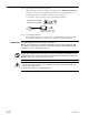
Step 2: Checking the remote interlock connector
Make sure that the short-circuiting pin is inserted into the “REMOTE INTERLOCK”
connector on the rear panel of the Display Unit. If this short-circuiting pin is not
inserted, laser emission is disabled, even if the power switch is on.
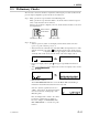
To emergency stop laser emission, refer to the following diagram.
Switch ON: Laser emission ON
Switch OFF: Laser emission OFF
(
Manufacturer: Sato Parts
)
Applicable connector: PJ-2
5V, 3mA
Short-circuiting pin
Switch
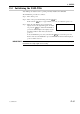
Step 3: Connecting the interface
For information about the procedure used to connect the interface, refer to Section
6.1, “RS-232C Interface” and Section 6.2, “Digimatic Output Unit Interface”.
IMPORTANT Note the following when making cable connections.
Always make connection or disconnection with the power cord unplugged. In addi-
tion, before connecting to the interface make sure that the power to all other units
connected or to be connected are also off.
Do not disassemble this unit. This unit is a precision instrument. Should it be disas-
sembled by the user, its accuracy can not be guaranteed even within the term of its
warranty. And, there will be a charge for repairs.
Observe the following to avoid electric shock.
1. Do not remove the protective cover on which the seal is stuck to. Otherwise, an
electric shock may result.
2. Do not remove the seal, shown at the left.