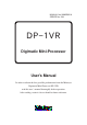
MANUAL No. 99MBE021A SERIES No. 264 DP-1VR Digimatic Mini-Processor User's Manual In order to obtain the best possible performance from the Mitutoyo Digimatic Mini-Processor DP-1VR, read this user’s manual thoroughly before operation. After reading, retain it close at hand for future reference.
THE MARKS USED IN USER'S MANUAL The meaning of symbol mark and contents describe with each symbol mark used in users manual is as follow. Notice on Safety In user's manual, to use exactly this unit, and to protect from yours and other peoples damage and property, several chart expression. The expression and meaning are as follows. ● Following expressions shown general notices, cautions and dangers, but not limited.
THE MARKS USED IN USER'S MANUAL ● The following marks show notice, exhibit of action/compulsion This marks show that there is contents urge the notice (include danger, warning. In the chart, concrete notice meaning is shown (left chart mean electrical shock) This mark express exhibited action. Concrete exhibited actions are drawn in the charts or near the charts. (left chart means exhibit of disassemble) This mark express the action under compulsion or direction.
THE MARKS USED IN USER'S MANUAL About several kinds of notice. Several kinds of "notice" which assist to obtain high reliable measured data show in following words. Important ◆ Notice indicates necessary information to achieve the purpose. Do not neglect this direction. ◆ If you do not follow this direction, there are the possibilities to loss or difficult to maintain the performance and accuracy of this unit. Notice This word indicates especially emphasize or supplementary information.
NOTICE ON SAFETY (PLEASE READ SURELY) To use safely, you should observe following. ◆ This unit is intended to be used for a general equipment (measuring equipment, or machine tool etc.) Do not use this unit for medical machine, aerospace vehicle, train or atomic power etc. which miss operation of this unit have possibility to injure the human body or treated human life. When you intend to use for such purpose, please inform to our company in advance.
NOTICE ON SAFETY (PLEASE READ SURELY) ◆ Please keep specified power source voltage. When this unit is used with not specified power source voltage. it causes damage of inside, fire or electric shock. ◆ Please do not put this unit at the place opened to direct sunshine or hot temperature. Inner temperature of this unit increases and causes fire. ◆ Do not put this unit close to wall. Inner temperature increases and causes malfunction.
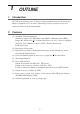
CONTENTS The marks used in this user's manual ........................................................................... i Notice on Safety (Please read thoroughly) ................................................................ iv WARRANTY ............................................................................................................. vi 1. OUTLINE ........................................................................................................ 1 1. Introduction .....................
CONTENTS 3. Basic operation 2 ................................................................................................. 25 3.1 Input of tolerance limit data ........................................................................ 25 3.2 Confirmation/renew of limit data ............................................................... 27 3.3 Release of limit data ................................................................................... 28 3.4 Data input, cancel, clear ........................
1 1. OUTLINE Introduction DV-1VR is an exclusive piece of data processing equipment that records data from a Mitutoyo digimatic tool so it can be statistically processed operation is easy and statistical results can be obtained quickly. 2.
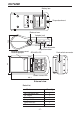
OUTLINE AA Ni-MH battery Alkaline battery LR6 Must use the following types of battery for battery operation. + − Mitutoyo Corporation MADE IN JAPAN Code No. Model Serial No. Power Battery box Strap attachment Release lever 43.9 INPUT OUTPUT ADAPTER OPEN 75.2 Adapter jack Input connector Output connector EXT.P DATA Foot switch connector FEED CE TOL.
2 1. SET UP Power supply ● Power is supplied to this unit by the AC adapter or four AA type Nickel Hydrogen batteries (Ni-Mh)/Alkali batteries (LR6) ● When the AC adapter is used while batteries installed, the power will be supplied from the AC adapter (batteries are not included). The AC adapter cannot charge the batteries, charge them with a dedicated battery charger, if necessary.
SET UP w Set the batteries. Be sure to set correctly the poles of the size AA Alkali batteries (LR6) or Nickel Hydrogen batteries (Ni -MH AA) e Close the battery box by the inverse process of q firmly until you hear the clicking sound. IMPORTANT ◆ Set the poles of batteries correctly. ◆ Do not use different kinds of batteries. ◆ Use either size AA Alkali batteries (LR6) or AA Nickel Hydrogen batteries (Ni-MH AA) ◆ Manganese batteries R6 cannot be used.
SET UP NOTE ◆ DP-1VR has no charger function. If you need to charge the batteries, a dedicated battery charger is needed. ◆ Battery life is about 10,000 lines, (using 1,600 m Ah Ni-MH, and print large, letter one time per 5 sec.) ◆ Battery life varies drastically in accordance with environmental conditions. 1.2 Connection of the AC adapter Connect the AC adapter to the DP-1VR. Skip this page when using batteries. DIGIMATIC MINI-PROCESSOR −NG POWER GO +NG POWER PRINTER CL TOL.
SET UP 2. Set of recording paper q OPEN ● Push the release lever downward ● Move the cover of recording paper upward, then open it. w ● Peel tape fixing the edge of record paper, then set the recording paper with a little bit of the paper pulled out. ● Set the core of the recording paper firmly in the holder. If the recording paper is wrinkled, it can cause the paper to jam while printing, so be sure it is straight.
SET UP ● When paper is set, be careful not to injure your hand by the paper cutter. IMPORTANT ◆ After setting the recording paper, be sure to press the ‘FEED’ key. This will perform a self-alignment thereby reducing paper jamming. ◆ When you open the recording paper cover, the printer head is exposed. Immediately after printing, the printer head is hot. Do not touch to avoid being burned. ◆ DP-1VR recording paper has superior characteristic of conservation, tolerance to chemicals and weather-proof.
SET UP 4. Other connection 4.1 Attachment of the strap Attach the strap to the DP-1VR as necessary q Take the sling off the hook. w Press the sling through the attachment point of the DP-1 as shown in the figure. Must use the following types of battery for battery operation. Alkaline battery LR6 AA Ni-MH battery Insert strap here Sling Hook e Hang the hook on the ring and pull out.
SET UP 4.2 Footswitch Data can be input by a foot switch. Connect to a foot switch connector, part No. 937179T (optional accessory) DIGIMATIC MINI-PROCESSOR −NG POWER GO +NG POWER PRINTER CL TOL. LIMIT STAT CE FEED DATA 4.3 RS-232C Cable • GO±NG judgement cable q RS-232C cable (part No. 09EAA084) RS-232C output can be obtained from DP-1VR and used for printing RS-232C, output of a linear scale counter. Connect the RS-232C cable to the DP-1VR output connector.
3 1. PARAMETER Parameter Parameter functions can customize the actions of the DP-IVR. Set up in accordance with the purpose. There are two kinds of parameter settings in accordance with connecting measuring equipment to DP-1VR. Select parameters in accordance with the measuring equipment used. 2. In the case of connecting calipers or micrometers Parameters are established for digimatic interfaces such as calipers or micrometers when connected to DP-1VR.
PARAMETER Table 1 Parameter in DP-1 MODE OrItem Setting der 1 PARAMET- Parameter clear ER CLEAR 2 SYSTEM DP-1 mode/Multi MODE 3 MODE0/MODE1/ WORK MODE2/MODE3 MODE 4 1200/2400/4800/ BAUD 9600/19200 RATE 5 N one/Even/Odd PARITY 6 7 8 9 10 11 12 DATA LENGTH PRINT SIZE Default Do not clear PARAMETER CLEAR PARAMETER NO CLEAR parameters Set DP-1 mode DP-1 Mode1 MODE0/MODE1 MODE2/MODE3 1200/2400/4800 9600/19200 NON/EVEN/ODD EVEN 7/8 7/8 7 Large/Normal LARGE/NORMAL SAVE/NORMAL LARGE When mode2 is set o
PARAMETER IMPORTANT ◆ Set DP-1 for action mode. NOTE ◆ When entered into parameter input mode, limit data is cleared. ◆ When parameters are cleared, they are set to default, except the date and time. Date and time are reset to 2001/1/1, 0:0. ◆ If a unit setting is selected, the unit set by this parameter is printed, regardless of the unit of the input data. In this case the unit information of input data is neglected. 3.
PARAMETER Table 2 Parameter in printing RS232CS output of counter OrItem Setting der 1 PARAMET- Parameter clear ER CLEAR 2 SYSTEM DP-1 mode/Multi MODE 3 MODE0/MODE1 WORK MODE 4 1200/2400/4800/ BAUD 9600/19200 RATE 5 N one/Even/Odd PARITY 6 7 8 9 10 11 12 DATA LENGHT PRINT SIZE POWER SAVE PRINT DENSITY BZ MODE TIME PRINT DATA FORMAT Do not clear PARAMETER CLEAR PARAMETER NO CLEAR parameters Set in MP mode DP-1 Mode1 1200/2400/4800 9600/19200 NON/EVEN/ODD 4800 EVEN 7 7/8 7 Large/Normal LARGE/NORMAL
PARAMETER IMPORTANT ◆ Set MP in action mode. ◆ Even if you do not perform statistical calculations, data processing axis should still be set. NOTE ◆ If the parameter is cleared, it is set to the default, except date and time. ◆ If the parameter is cleared, date and time is reset to 2001/1/1, 0:0 ◆ Unit information is not sent out from the linear scale counter. So, if the unit is not set, the unit is not printed in the data. ◆ It’s possible to connect with K series counter only.
PARAMETER 4. Example of parameter settings Procedure to correctly set parameters is shown. 4.1 DP-1 parameter setting procedure By entering the parameter mode, parameters can be set. To enter the parameter setting mode when the electrical power is OFF, simultaneously press 'DATA' key and 'POWER' key. Then, the unit will enter the parameter mode. In the parameter input mode, the following key operations can change setting details.
PARAMETER Table 3 Example of parameter setting procedure Key operation ‘DATA’ + ‘POWER’ starting Print Comments PARAMETER SETUP MODE SYSTEM MODE WORK MODE BAUDRATE PARITY DATA LENGTH PRINT SIZE POWER SAVE PRINT DENSITY BUZZER MODE TIME PRINT DATE FORMAT DATE TIME UNIT : DP-1 : MODE1 : 4800 : EVEN :7 : LARGE : NORMAL : NORMAL : ON : ON : YYYY/MM/DD : 2000/ 1/ 1 : 10:10 : AUTO PUSH DATA PUSH STAT : DATA FIX & GO : DATA CHANGE STAT DATA PARAMETER NO CLEAR PARAMETER CLEAR PARAMETER CLEAR SYSTEM MODE : D
PARAMETER Key operation DATA CE CL PRINTER STAT DATA CL PRINTER STAT DATA Print Comments CE : DAY CL : MONTH PRINTER : YEAR PUSH EACH KEY TO INCREMENT DATE 2001/1/1 'CE' key increments date Rotate 1~31 'CL' key increments month Rotate 1~12 'PRINTER' key increment change by rotating 00~20 'STAT' key print date setting is not printed by 'CE' 'CL' 'PRINTER' key operations Finish setting by the 'DATA' key YYYY/MM/DD : 2001/2/2 CL : MIN PRINTER : HOUR PUSH EACH KEY TO INCREMENT TIME 11:11 'CL' key incremen
PARAMETER Key operation DATA Print SYSTEM MODE WORK MODE BAUDRATE PARITY DATA LENGTH PRINT SIZE POWER SAVE PRINT DENSITY BUZZER TIME PRINT DATA FORMAT DATE TIME UNIT Comments : DP-1 : MODE1 : 4800 : EVEN :7 : NORMAL : NORMAL : NORMAL : ON : ON : YYY/MM/DD 2001/2/2 11:11 : AUTO Printed summary of set parameters IMPORTANT ◆ Parameter input is memorized through the last operation. Do not stop the operation if not completed. ◆ Setting the date and time is written when the time input is set.
4 SUMMARY OF FUNCTIONS 1. Key functions Function Mode3 Key CL (clear key) CE (cancel key TOL.LIMIT (limit key) STAT (stat key) FEED (feed key) DATA (data key) PRINTER ON/OFF (printer on/off key) POWER (power key) During After subgroup Subgroup measuring is complete measuring ● Clears only measured data. ● Re-input from ● Clears only (settings remain) push firmly No.
SUMMARY OF FUNCTION 2. Function of each mode Mode 0 Function To print measured data, and judge tolerance. Mode 1 Mode 2 ● Function Function To print measured To print D-chart (graph that visibly shows the data, judge tolerance, perform variation of measured statistical calcula- data), perform statistical tions, and generate calculations, and generate histogram. histogram. a) Limit setting If you record judgment limits and prepare a histogram, push ' TO L. LIMIT' key. If you do not, go to measure.
SUMMARY OF FUNCTION 3. Timer input function This function is used when you intend to take in data automatically from measuring equipment in the same interval. Press the PRINTER ON/OFF key, and at this state pushing the PRINTER ON/OFF key enters the unit to this function, and the following pressed key can set the interval time. When you finish this function, press the PRINTER ON/OFF key, while pressing the ‘CL’ key. NOTE 1.
5 1. OPERATION Power ON/OFF Operation of power ON/OFF. Operation Power ON Key Print POWER * DP-1VR * * MODE-1* DATE 2000/ 2 /2 TIME 13:36 Power OFF POWER Press more than 2 sec. and release. NOTE ◆ To prevent mis-operation, power can be cut only when the 'POWER' key is pressed more than 2 sec. Note that the power can not be cut if the pushing time is short. ◆ Contents of printout are a little different in the case of using extended letter size from that of the standard letter size.
OPERATION 2. Basic Operation 1 Basic operations that do not have set limits are shown. Similar operations are conducted in Mode0, Mode1, Mode2 also. 2.1 Data input, cancel, clear Function ● ● ● ● ● ● Power ON Data input Data can be input with the foot switch interval timer or the 'DATA' key Data cancel Cancel previous input data. Data all clear Clear all input data Time printing Print date and time Statistical calculation Statistically calculates input data.
OPERATION IMPORTANT ◆ Recording paper of DP-1 is superior to characteristics of conservation and tolerance to chemicals, but it shares limits with other thermal papers. In the case of long storage (more than 5 years), or if used for public documents, you should make a photocopy. ◆ If cutting fluid comes in contact with the recording paper, and those documents will be stored for a long time, it is recommended to photocopy. ◆ In the case of mode 0 Statistical calculation can not be conducted.
OPERATION 3. Basic operation 2 Operation procedures when tolerance limits are set is shown. Similar operations are conducted in mode 0, mode 1 and mode 2. 3.1 Input of tolerance limit data Operation to input limit data. Data is input through the connection of the measuring equipment to the DP-1VR. ● Power ON Tolerance limit input mode Tolerance limit input mode can be entered the 'TOL.LIMIT' key. Limit number can be changed from 5 by the 'STAT' key.
OPERATION NOTE ◆ To enter the tolerance limit input mode, q it is necessary that data is not input just after power on, or w all data is cleared by operation of the 'CL' key. ◆ In limit mode, limit data can changed by operation of the 'STAT' key. Maximum limit data of 5 is recorded. Reset limit data as necessary. ◆ When limit data is input by selecting the number of limit data already set, new data is saved and old data removed. ◆ Limit data remains in memory even if the power is cut.
OPERATION 3.2 Confirmation/reset of the limit data The operation of confirming contents of 5 of tolerance limit data and resetting tolerance limit data to use. ● Confirmation and reset of limit TOL.LIMIT data. If limit data is not input or it is cleared by the 'CL' key, the operation is possible. LIMIT MODE* *LIMIT DATA 2* LSL 12.36 mm USL 25.67 mm TOL 13.31 mm Tolerance limit data is renewed by STAT 'STAT'. *LIMIT DATA 3* LSL 12.56 mm USL 25.89 mm TOL 13.
OPERATION 3.3 Release of the limit data Operation to release the tolerance limit data. It is conducted when the limit data is not necessary. ● Limit release Press the 'CL' key to release tolerance limit data. Limit data is released. TOL.LIMIT *LIMIT DATA 1* LSL 12.36 mm USL 25.67 mm TOL 13.
OPERATION 3.4 Data input, cancel, clear Table 2 DP1 mode1, operation example 2 Function ● Operation Power ON Print POWER * DP-1VR * * MODE 1* DATE 2000/ 2/ 2 TIME 13: 35 PRINTER ON/OFF + DATA CE *LIMIT DATA 1* LSL 12.36 mm USL 25.67 mm TOL 13.31 mm DATE 2000/ 2/ 2 TIME 13: 35 * CANCEL * ● Data input All input data is cleared. CL * CLEAR * ● Data input Limit judgment is conducted for the input data, displayed (LED) and printed. DATA H 1 12.00 mm DATA 2 26.25 mm DATA G 3 32.
OPERATION Input data Function Statistical calculation ● Statistical calculations are conducted, when 9999 or more data is input. Operation Print PART NO. DATE 2000/ 2/ 2 TIME 13: 35 NAME STAT *RESULT* N MAX MIN R X σn σn-1 56 81.26 mm 25.66 mm 55.60 mm 54.23 mm 12.5635 mm 13.5897 mm −NG +NG P Cp Cpk 2 4 18.56% 0.45670 0.30000 *HISTOGRAM* LSL 12.36 mm USL 25.67 mm TOL 13.
OPERATION Function Operation Print NNN +NG □ = A B C D E F G H I J 4| □□ 2 12.3600p 13.6910p 15.0220p 16.3530p 17.6840p 19.0150p 20.3460p 21.6770p 23.0080p 24.3390p 25.6700p IMPORTANT ◆ DP-1 recording paper has superior characteristics of conservation and tolerance to chemicals, but it shares limits with other thermal papers. In the case of long storage (more than 5 years), or if used for public documents, you should make photocopy.
OPERATION 4. Mode 3 Example mode3 operation Function Power ON Operation Print POWER Initiate measurement of a subTOL.LIMIT group Transfer a subgroup to measuring mode. Data receiving DATA (Subgroup measure mode) DATA DATA Data cancel CE Cancels prior input data. ('CL' key pressed during measurement of a subgroup) Subgroup data is all cleared. CL Data in subgroup is all cleared, and are measured again from No.1 data.
OPERATION Function Measure next subgroup Data input Finish measurement of subgroup and calculate X-R of subgroup Operation TOL.LIMIT DATA DATA DATA STAT Print SUB GR. 2 Input data from measuring equipment. 1 12.00 mm 2 26.25 mm 3 32.56 mm X 0.92335 mm R 2.77568 mm PART NO. DATE 2000/ 2/ 2 TIME 13: 35 NAME *CONTROL LIMIT* DATE 2000/ 2/ 2 TIME 13: 35 Calculation of control limits is STAT carried out from all the sub-group data which has been input, and the result is printed.
OPERATION 5. Print RS232C of counter Function Power ON If parameter time stamp is 'OFF', data and time are not printed. ● ● Time stamp Data cancel Prior data input is canceled. ● Data all clear All input data is cleared. ● Data input Limit judgment is conducted for input data and displayed (LED) and printed. Meanings of the symbols are as follows.
OPERATION Function Operation Print R X σn σn-1 −NG +NG P Cp Cpk 55.60 54.23 12.5635 13.5897 2 4 18.56% 0.45670 0.30000 *HISTOGRAM* LSL 12.36 USL 25.67 TOL 13.31 DIV 10 −NG LSL NNN A B C D E F G H I J USL NNN +NG □ = A B C D E F G H I J - 35 - 2| □ |NNNNNN 2| □ 4| □□ 5| □□ 8| □□□□ 9| □□□□ 11| □□□□□□ 4| □□ 9| □□□□ 5| □□ 4| □□ |NNNNNN 4| □□ 2 12.3600p 13.6910p 15.0220p 16.3530p 17.6840p 19.0150p 20.3460p 21.6770p 23.0080p 24.3390p 25.
6 OTHER NOTES In order to ensure data reliability of the SDP interface, DP-1VR reads the data twice. Some models (KC counter with code out unit No. 09CAA462 etc.) are incapable of performing the above data checking routine. For those models, you must perform the following procedures by changing the interface mode. Interface mode is interchangeable with the former products (DP-1HS) by setting it for COMPATIBLE.
7 MAINTENANCE Daily maintenance of DP-1VR 1. Clean printer head When dust collects on the printer head, print quality is adversely affected, and sometimes printing is impossible due to damage to the printer head. It is recommended cleaning the printer head periodically. Cleaning method: After opening the printer cover the printer head can be seen. Rub the printer head with a cotton swab soaked in a little alcohol. After that, wipe off the remaining alcohol lightly with a dry cotton swab until dry. 2.
MAINTENANCE Paper sensor Printer head Paper cutter - 38 -
8 1. ERROR MESSAGE Alarms concerning electric power Table 1 Power related alarms Condition Abnormally high voltage Normal Slightly low voltage; caution In the case that voltage drops the battery capacity is reduced. Abnormally low voltage In the case that voltage is low and becomes impossible. Voltage detection more than 10.0V 10.0 ~ 4.5V 4.5V ~ 4.2V Power LED flash Data ON and OFF input patern 0.6 sec on, 0.6 sec Impossible off repeat Always on Possible 1.5 sec OFF, 0.3 sec Possible ON 0.3 sec OFF, 0.
ERROR MESSAGE 2. Other alarms Table Error alarm of DP-1VR Kind of alarm ● System error Symptom Possible cause ● Fatal error of DP-1 occurred. ● Operating temperature is too high or too low. *OVER FLOW* ● Overflow ● It is beyond ● is printed. possible calculating area. ● No paper ● LED of −NG, ● No recording +NG flashes on and paper. off. ● A red line appears on the record paper. ● Cover open ● LED of −NG, ● Cover of (Head up) +NG flashes on and recording paper is off. open.
ERROR MESSAGE Kind of Symptom Possible cause Remedies alarm Error in *POINT ERROR* Decimal point ● It is printed when the decimal decimal point position of input point position is different from data is different. initial input data. The decimal point position should be the same as the initial data. ● Different decimal point position from set limit data is input. Input data of the same decimal point position as limit data.
9 1. CALCULATION METHOD Significant figure Significant figures of calculation are as follows. When significant figures (figures after the decimal point) of input data are A, significant figures are displayed.
CALCULATION METHOD 2. Overflow and calculation error ● Overflow and calculation error Overflow conditions of DP-1VR and calculation error are shown below: Overflow of DP-1VR is different due to mean value and amount of data. This is shown in the graph overflow condition. ● Viewpoint of graph If mean value 10 m is measured with 2 figures after the decimal point (by caliper etc.), how much of data can be measured, is checked. q Data 10000.00 is changed to 1000000 as no decimal point.
CALCULATION METHOD NOTE ◆ Mean value of the data shows the state when the decimal point of the data is neglected. Ex 10.00 is changed to read 1000 3. Calculation error detail Calculation error of DP-1VR is shown below: Calculation error of DP-1VR is defined as follows. q Last figure ±1 count. Graph expresses the inside of the overflow limit of the calculation preciseness. Dispersion of data is set at ±5% of the mean value.
CALCULATION METHOD 4. Calculation formula 4.
CALCULATION METHOD 4.2 Calculation Mode3 N: Data count MAX: Maximum value of data MIN: Minimum value of data n: Number of subgroup A2 : Refer to table D3 : Refer to table D4 : Refer to table Maximum number of data in each subgroup is 10 Table 3 Mode3 table of variables SAMPLE SIZE n A2 2 3 4 5 6 7 8 9 10 Sign 1.880 1.023 0.729 0.577 0.483 0.419 0.373 0.337 0.308 D3 D4 0.076 0.136 0.184 0.223 3.267 2.574 2.282 2.114 2.004 1.924 1.864 1.816 1.
10 OUTPUT By connecting the optional cable (NO. 965465) to the OUTPUT connector located at the side of this unit, either GO/±NG judgment for the input data or measured data in RS-232C format can be output through the OUTPUT connector. 1. Output of GO/±NG Judgment When the optional GO/±NG judgment result output cable (NO. 965516) is connected to this unit, and it is in MODE0, MODE1, or MODE2 with the upper and lower tolerance limits set. These judgment results will be output though an open collector.
OUTPUT 2.1 Communication Specifications Output Signal Level: TTL Level Communication Method: Half-Duplex Transmission Speed: 1200, 2400, 4800, 9600, 19200 Bit Construction: Start bit 1 bit Data bit 7/8 bits Parity Check EVEN/ODD/NONE 2.2 Data Format D1 D2 D3 D4 D5-D12 D13 CR DATA (Floating decimal point) D12LSD Sign: positive (+) and negative (-) Measuring item: A Channel No.: 1 Code No.
OUTPUT 2.3 Error Code D1 D2 D3 D4 CR Error Code: 1 2 9 Data entry error Entry does not satisfy the specified format System error Head temperature error Power voltage error Over flow Paper error Channel No.: 1 Error Format: 9 2.4 Data request command D1 D2 CR Code No.
11 TROUBLESHOOTING Checks and Remedies-Before diagnosing a problem as a defect, check the following information. When the DP-1VR malfunctions, diagnose the problem and remedy of the situation with the aid of the following table. If the problem still persists, please contact your dealer or the nearest Mitutoyo sales office. (For the addresses, refer to the end of this manual.) The warranty period of the DP-1VR is one year from the date of purchase for use.
TROUBLESHOOTING Symptom Possible cause Remedies When printing, the ● Manganese dry cells are used by ● Use properly charged size AA Nickel Hydrogen battery (Ni-Mh) DP-1VR unexpect- mistake or Alkali battery (LR6) edly returns to the initial state seen ● Peeling or poor fitting of the seal ● Correct the peeling or poor after the power is is present on the battery pole fitting of the seal turned ON. ● The specified AC adapter is not ● Use the dedicated AC adapter Printing is too used.
12 SPECIFICATIONS Item Description Remarks Code No. Printing Method Character format Printing Speed Printing line numbers per printing roll Power supply 264-504 Line thermal 384 dot 36 × 24 (Large) 24 × 14 (Normal) 0.5 sec.
SPECIFICATIONS Item Description Remarks 100000 9999 10 × 9999 = 99990 (Sample size × Number of sub-groups = total number of measurements) 5 sets of limit data Output function Measured data (RS-232C, TTL level) GO/±NG Judgment results (+NG, GO, −NG) Timer-controlled 0.25 sec, 1 sec, 5 sec, 30 sec, 1 min, 30 data input min, 60 min. Standard accesso- AC Adapter ries Processing capability Recording paper: 1 pc.
SPECIFICATIONS SERVICE NETWORK MTI Corporation New Jersey Office 18 Essex Road, Paramus, N.J. 07652, U.S.A. TEL: (201)368-0525 TELEX: 134317 FAX: (201)343-4969 Mitutoyo France S.A.R.L., Agence de Lyon Bat L133, avenue du Dr. Georges Levy 69200 VENISSIEUX TEL: (16)78752010 Detroit Office 45001 Five Mile Road, Plymouth, M? 48170, U.S.A. TEL: (313)459-2810 FAX: (313)459-0455 Mitutoyo Italiana S.R.L. Corso Europa No.
Mitutoyo Corporation 20-1, Sakado, 1-chome, Takatsu-ku, Kawasaki, Kanagawa 213-0012, Japan Printed in Japan