
User's Manual
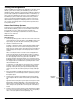
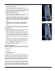
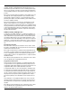
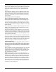
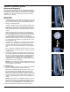
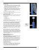
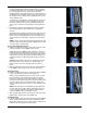
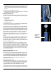

Fig. 51
Fig. 52
Fig. 53
After connecting the FST, it is normal to have air trapped in the
f
uel lines and flowmeter. Cycling the ignition switch (or cranking
the engine briefly) with the flow control valve in the BYPASS posi-
tion can help purge air from the system. Once fuel fills the
flowmeter and flows through the bypass hose, return the valve to
the OPEN position. The bypass hose must be routed and secured
into an approved fuel container before operating the flow control
valve in BYPASS mode.
To perform an accurate diagnosis using the FST, the car must be
running in order to provide the correct operating voltage to the
f
uel pump. Testing the fuel system by activating the fuel pump
using a scan tool will cause the fuel pump to severely under-per-
form.
3. Note the fuel system pressure indicated on the pressure gauge,
and compare it with the vehicle manufacturer’s specification
(Fig. 51).
Typical electronic fuel injection system pressures range from 30 to
60 PSI (205 to 410 kpa) depending on the vehicle being tested.
Always use the recommended vehicle service information, proce-
dures, and pressure specifications for the specific vehicle being
tested.
NOTE: The flow of fuel passing through the tester represents only
what the engine is using at idle. It will be negligible and most likely
not even register on the flowmeter.
Pressure Demand (Dead-head) Test
4. With the car idling, rotate the flow control valve on the side of the
flowmeter towards the 90° CLOSED position (Fig. 52).
Rotating the valve to CLOSED creates a restriction to the flow of
fuel through the tester. Watch the pressure gauge, as the valve is
rotated, the pressure should increase. Note the pressure when the
valve is fully closed. A good fuel pump should be capable of pro-
ducing pressure 50% to 100% higher than the rating of the fuel
system.
Caution: Never rotate the valve to the closed position for longer
than a brief instant. This is referred to as “dead-heading” the
pump, and can cause serious damage to the fuel system or
pump.
5. After noting the peak pressure, rotate the flow control valve back
to the OPEN position, and proceed to the flow demand test.
Flow Demand Test
6. With the car idling, rotate the flow control valve past the CLOSED
position to the BYPASS position pointing up (Fig. 53).
With the valve in the BYPASS position, the flow of fuel is routed
through the bypass port located above the valve, through the
bypass hose, and into the reservoir. All restriction to the flow of
fuel is removed. This allows the pump to output its maximum flow,
the value of which can be read on the flowmeter. The free flow
output of a typical fuel pump is between .7 and 1.0 GPM (2.5 and
4 LPM).
NOTE: Turning the valve to the full BYPASS position will prevent
fuel from flowing to the engine. If left in the BYPASS position for
too long, the engine will stall. If this happens, simply return the
valve to the OPEN position and restart the vehicle.
7. After noting the peak pressure, return the flow control valve to the
OPEN position, and proceed to the capability test.
Peak Demand Test
8. Note the vehicle’s engine size and maximum engine speed (RPM).
Refer to the Maximum Engine Fuel Volume Requirements table
(Appendix A), and use the size and speed values to determine the
maximum fuel volume requirement of the engine.
Form 824127 Page Number - 29