
Instructions / Assembly

4
2
3
6
10
11
9
8
1
7
5
LENA
H514704S, H514704L
INSTALLATION INSTRUCTIONS
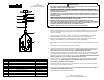
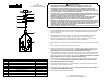
FIXTURE INSTALLATION
1. Attach the CROSSBAR (1) onto the junction box using the MOUNTING SCREWS (2). This fixture is designed to
be mounted on standard round or octagon junction box. The junction box must be securely mounted to the
structure of the building.
2. Open the end link on the CHAIN (9) and attach to the loop on the FIXTURE ASSEMBLY (10). Hang the
FIXTURE ASSEMBLY (10) on the CHAIN (9) at your desired height, and remove excess CHAIN.
3. Feed the wire through the CHAIN (9) , SCREW COLLAR (5), CANOPY (6), SCREW COLLAR LOOP (7),
NIPPLE (8), and CROSSBAR (1), and screw the NIPPLE (8) onto the CROSSBAR (1).
4. Open the top link on the CHAIN (9), and Hang the FIXTURE ASSEMBLY (10) to the SCREW COLLAR LOOP
(5).
5. Cut off excess wire, and strip the insulation off the end of the leads.
6. Attach the Ground wire (Green) to the ground inside the junction box (Generally green or bar copper wire) or
the GROUND SCREW (3) on the MOUNTING PLATE (1). NEVER CONNECT GROUND WIRE TO "HOT"
WIRE! FAILURE TO FOLLOW THIS COULD RESULT IN SERIOUS INJURY OR DEATH!
7. Connect the white fixture lead to the neutral (Generally white) wire in the outlet box. Fasten the wires together
with an approved fastener (WIRE NUT) (4). Starting 1" below the fastener, tightly wrap the connection with
electrical tape so that the connections seals the end of the fastener. MAKE SURE THERE ARE NO EXPOSED
WIRE OF STRANDS THAT COULD CAUSE A DANGEROUS SHORT CIRCUIT!
8. Connect the black fixture leads to the hot (Generally black) wire in the junction box. Fasten the joined wires
same as previous step. NEVER REVERSE HOT AND NEUTRAL WIRES. FAILURE TO FOLLOW THIS
COULD RESULT IN SERIOUS INJURY OR DEATH!
9. Push the wires back into the junction box. Lift up the CANOPY (6) up to the ceiling, and screw the SCREW
COLLAR LOOP (7) onto the SCREW COLLAR (5).
10. Screw the BULB (10) up into the SOCKET of the fixture.THIS FIXTURE IS RATED FOR 60 WATT LAMP. DO
NOT EXCEED THE RECOMMENDED WATTAGE!
11. Restore power to the outlet at the breaker or fuse box.
www.hvlgroup.com
Questions? We're here to help!
Contact us at CustomerService@hvlgroup.com
ITEM DESCRIPTION
PART NUMBER
1 CROSSBAR HDW-H514701S
2
MOUNTING SCREW
HDW-H514701S
3
GROUND SCREW HDW-H514701S
4
WIRE NUT
HDW-H514701S
5
SCREW COLLAR HDW-H514701S
6
CANOPY CPY-H514701S
7 SCREW COLLAR LOOP HDW-H514701S
8
1/4 NIPPLE
HDW-H514701S
9 CHAIN CHN-H514701S
10 FIXTURE ASSEMBLY
FAS-H514701S, L
11 BULB NOT INCLUDED
HUDSON VALLEY LIGHTING
ATTENTION PRUDENCE
· DÉBRANCHEZ L'ALIMENTATION AVANT DE REMPLIR OU DE CÂBLER LE LUMINAIRE. LISEZ
COMPLÈTEMENT TOUTES LES INSTRUCTIONS AVANT DE COMMENCER L'INSTALLATION
· POUR ÉVITER LE RISQUE D'INCENDIE OU D'ÉLECTROCUTION, LE LUMINAIRE DOIT ÊTRE INSTALLÉ
CONFORMÉMENT À TOUS LES CODES ÉLECTRIQUES/DE CONSTRUCTION NATIONAUX ET LOCAUX
APPLICABLES. L'INSTALLATION ET L'ENTRETIEN DE CET APPAREIL DOIVENT ÊTRE EFFECTUÉS PAR UN
ÉLECTRICIEN AGRÉÉ OU UN TECHNICIEN CERTIFIÉ FORMÉ EN USINE.
· CALIFORNIE PROP 65 : CET APPAREIL D'ÉCLAIRAGE CONTIENT DES PRODUITS CHIMIQUES CONNUS PAR
L'ÉTAT DE CALIFORNIE POUR PROVOQUER LE CANCER, DES MALADIES CONGÉNITALES ET/OU D'AUTRES
DOMMAGES À LA REPRODUCTION. LAVER LES MAINS APRÈS UTILISATION.
· RETIRER LE LUMINAIRE, LES PIÈCES ET LE(S) SAC(S) DE PIÈCES DU CARTON. AVANT DE JETER LE
CARTON, VÉRIFIEZ DOUBLE POUR VOUS ASSURER QUE TOUTES LES PIÈCES SONT TROUVÉES.
INSPECTER LE LUMINAIRE AVANT L'INSTALLATION POUR TOUT DOMMAGE AU LUMINAIRE.
· GRADATION : LE LUMINAIRE PEUT ÊTRE CONTRLÉ PAR UN DISPOSITIF DE GRADATION MURALE. UTILISER
UNIQUEMENT UN GRADATEUR TRIAC/ÉLECTRONIQUE. ASSUREZ-VOUS QUE LE CARTON EST MARQUÉ
POUR UNE UTILISATION AVEC UNE SOURCE DE LUMIÈRE FLUORESCENTE À INCANDESCENTE COMPACTE
UNIQUEMENT. CEUX-CI PEUVENT ÊTRE FOURNIS PAR VOTRE DISTRIBUTEUR ÉLECTRIQUE LOCAL,
CENTRE À DOMICILE OU MAGASIN DE QUINCAILLERIE.
· VEUILLEZ NETTOYER UNIQUEMENT AVEC UN CHIFFON DOUX ET SEC ! N'UTILISEZ PAS DE NETTOYANTS