MJK Automation A/S Byageren 7 DK-2850 Nærum Denmark Tel.: +45 45 56 06 56 Fax: +45 45 56 06 46 mjk@mjk.com www.mjk.com Ultrasonic Level Transmitter and Sensor New All MJK’s newest ultrasonic sensors covered and described in this manual User Manual GB Shuttle Manual 100316 1 New setup procedure. See page 14 for choosing correct sensor type at initial setup.
Ultrasonic Level Transmitter and Sensor IMPORTANT The first time power is applied to the mounted Shuttle® level transmitter and ultrasonic sensor, the level transmitter must be configured for the connected sensor type. The procedure is located on page 14, "Applying power". If, at a later time, another or a newer sensor type is connected to the transmitter, the level transmitter must be re-configured accordingly. The procedure is located on page 69, "Appendix F New sensor / changing sensor".
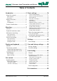
Ultrasonic Level Transmitter and Sensor Table of Contents Introduction..................................5 Basic settings.............................16 Units of measurement...........................17 Sensor to zero point distance................18 Level read-out.......................................19 The well is not empty.............................19 mA output.............................................20 Relay outputs........................................21 Selection of relays 1 and 2............
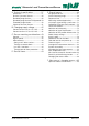
Ultrasonic Level Transmitter and Sensor A Technical specifications................37 E Special menus.............................46 Dimensions...........................................37 Shuttle® Ultrasonic Sensors...................38 Standard Range Version........................38 Standard Range Version/FM Approved..39 Extended Range Version.......................40 Chemical Resistant Version...................41 Bar graph read-out................................47 Active measuring range.............
Introduction Introduction Illustrations Thank you for choosing a Shuttle® Ultrasonic Level Transmitter. All the Shuttle® display read-outs are illustrated in this manual. Some of the display segments will flash, and in this manual the display read-outs with flashing segments are coloured white and the fixed segments are coloured black. We have done everything possible to make a level transmitter that can fulfill all your demands.
Introduction Safety instructions Product identification 1: Read this manual carefully. Check that the item(s) delivered corresponds to the ordered item(s). The item number is printed on a label that is sticked onto the packing. Shown below is the label for a delivery including a level transmitter and a ultrasonic sensor: 2: Be aware of the environment at the installation site. Wear necessary protective equipment and follow all current safety regulations.
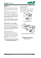
Mounting Mounting Mechanical mounting Level transmitter General Shuttle measures the level by sending an ultrasonic signal against the surface and measuring the delay time of the received echo. ® Shuttle® is in IP65 enclosure and can be mounted outdoors directly on a wall, a railing or a banister with mounting plate 200240 and universal bracket 200205.
Mounting The ultrasonic sensor is equipped with a nut for bracket mounting. Note the recess on the nut - it must be fitted safely in the bracket for firm fixing to the bracket: Ultrasonic sensor Two things are extremely important when mounting the ultrasonic transmitter: (See also appendix C!) 1: It should be mounted securely. 2: It should be mounted absolutely vertical. Use a spirit level in TWO directions.
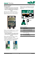
Mounting Electrical mounting Level transmitter Mount the wires according to the terminal numbers on the reverse side of the green plastic film: The Shuttle® must not be connected to the power supply before the ultrasonic sensor is mounted and connected correctly. When the cover has been removed, the green plastic film with the menu symbols is tipped up to gain access to the terminals.
Mounting Ultrasonic sensor Cutting the cable The ultrasonic sensor is delivered as standard with 12 metres of cable. The ultrasonic sensor can be delivered with up to 100 m of cable on order, or the standard 12 m cable can be extended to max. 100 m. The cable is delivered with the wires stripped as shown with the black wire (no. 5) soldered to the shield: The cable is a special low capacity cable, so extensions should always be made with the same type of cable.
Display and keyboard Display and keyboard General The keyboard is used only for the initial programming of the Shuttle®, and is therefore hidden behind the front lid. The keys are marked with symbols indicating their function. The same symbols are used throughout this manual under the explanation of the individual menus. LCD-display with symbols for indication during programming, servicing and normal operation.
Display and keyboard The display symbols The different display segments indicates the actual level, the state of the output relays etc. during normal service and indicates limit values, selection of measuring unit and other settings during programming. The segments shown will be lit when Shuttle® are in normal service. The segments shown will be lit during programming of the Shuttle®. Displayed during normal service Displayed during programming Numerical read-out of the actual level.
Display and keyboard The keyboard From the Shuttle® keyboard the keys marked A - F (➀) gives access to 21 menus divided in 6 basic settings and 15 special settings. There is direct access to the menus for basic settings by pressing one the keys A to F. See appendix E for instructions for access to the special settings. When a menu has been selected, settings are made with the UP and DOWN keys and the selection is confirmed with the ENTER key (➃) whereafter Shuttle® reverts to normal read-out.
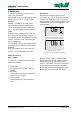
Display and keyboard Get started Applying power When Shuttle® is connected to power for the first time, the following texts (Choose Sensor Press Enter) will appear across the display: Press "Enter" once to select the required sensor type. Sensor type selection When "No Sensor" (no S) is displayed, press the 'Up' or 'Down' arrow key to leaf through the different sensor types: 2005xx and 2006xx. When the required sensor type appears on the display (here: 200570), press "Enter" once.
Display and keyboard At the same moment Shuttle® registers an echo, the zero point is automatically set to the level that is present in the tank or well. Furthermore, the mA output is set to 4 mA at the current zero point and 20 mA at a level corresponding to a distance of 35 cm from the ultrasonic sensor.
Display and keyboard Basic settings The automatic setting of the zero point and the mA output made by Shuttle® during initial startup may be adequate. If changes of the zero point read-out and mA output setting should be necessary, and when Shuttle® is to be used as a pump controller or for level monitoring, an additional 5 settings should be made. These settings are described in detail on the following pages. Proceed with set-up in the order listed below: 1: Setting units of measurement See page 17.
Display and keyboard Units of measurement If the measuring unit is changed, all other values in menus and settings will automatically be converted to the new measuring unit. In this example the measuring unit is changed from metres to feet. The settings will be rounded off automatically. Select unit with the arrow keys. The dot indicates the position of the decimal separator. Note: 2,00 m 6,59 ft 0,00 m 0,0 ft 'mm' or 'in' cannot be selected if it could cause overrun in the display read-out.
Display and keyboard Sensor to zero point distance The level read-out (zero point) can be adjusted as required. This is almost always required if the well was not empty during initial startup. Note: The learning function settings will be erased and the relays will be deactivated if the zero point setting is changed. In this example, the level read-out is changed to be 1.50 ft from the bottom of the well / tank. Set the new zero point with the arrow keys.
Display and keyboard Level read-out The well is not empty With this function the level read-out can be increased or decreased on demand. This is almost always required if the well was not empty during initial startup. Note: The learning function settings will be erased and the relays will be deactivated if the zero point setting is changed. In this example, the actual level is 80 cm, but Shuttle® reads out 0 m. Select the desired level read-out with the arrow keys.
Display and keyboard mA output When Shuttle® is connected to the power supply for the first time, the mA-output is automatically set to provide 4 mA at zero level and 20 mA at a level corresponding to 35 cm below the ultrasonic transmitter. In this example the range of the mA output is changed from 0 - 1,65 m to 0,5 - 1,5 m. Changes made will not affect the relay settings. Note: Both values can be set over the whole range thus making it possible to decrease the mA signal at rising levels and vice versa.
Display and keyboard Relay outputs Selection of relays 1 and 2 Three functions are available: - pump control with alternation of two pumps - level control - system alarm Note: If Pump Control is selected, the start and stop settings cannot be set any closer than 10 cm. If Level Control is selected, the start and stop settings cannot be set any closer than 1 cm. Select the desired function with the arrow keys. Pump control: Continue on the facing page.
Display and keyboard Pump control with relays 1 and 2 Start and stop level for pump no. 1 is set to 1,00 and 0,75 m respectively. 1,00 m 0,75 m Select the time delay for relay 1 with the arrow keys. Start and stop level for pump no. 2 is set to 1,25 and 0,50 m respectively. 3.75 ft 1.50 ft Select the time delay for relay 2 with the arrow keys. With these start and stop levels Shuttle® is now configured for pumping out and reverts to normal read-out.
Display and keyboard Level control with relay 1 In this menu the level for activation (set) of relay 1 is changed from 1,65 to 1,00 m and deactivation (reset) of the relay output is changed from 0,00 to 0,50 m. Select the activation (set) level for relay 1 with the arrow keys. 1,00 m (activate) 0,50 m (deactivate) Select the deactivation (reset) level for relay 1 with the arrow keys. Select the time delay. Select relay mode. ('n.c' = normally closed, 'n.o' = normally open).
Display and keyboard System alarm on relay 1 In this menu the time delay is set for the activation of relay 1 when a system error occurs together with the reset position of the relay (normally open / normally closed): Select the time delay. Select relay mode. ('n.c' = normally closed, 'n.o' = normally open). Note: If 'n.c' is selected, Shuttle® will also give alarm in case of power failure. Shuttle® reverts to normal read-out.
Display and keyboard Selection of relay function for relay 2 Two functions are available: - level control - system alarm Note: Both relays are already in use if pump control has been selected earlier. Select the desired function. Level control: Continue on the facing page. System alarm: See page 27.
Display and keyboard Level control with relay 2 In this menu the level for activation (set) of relay 1 is changed from 1,65 to 1,00 m and deactivation (reset) of the relay output is changed from 0.00 to 1.50 ft. Select the activation (set) level with the arrow keys. 1,00 m 0,50 m Select the deactivation (reset) level with the arrow keys. Select the time delay. Select relay mode. ('n.c' = normally closed, 'n.o' = normally open). Shuttle® reverts to normal read-out.
Display and keyboard System alarm on relay 2 In this menu the time delay is set for the activation of relay 1 when a system error occurs together with the reset position of the relay (normally open / normally closed): Select the desired time delay. Select relay mode. ('n.c' = normally closed, 'n.o' = normally open). Note: If 'n.c' is selected, Shuttle® will also give alarm in case of power failure. Shuttle® reverts to normal read-out.
Display and keyboard Start of the learning function First time activation With this function Shuttle® learns if there are any disturbances in the well or tank that could appear as a true echo. Disturbances can result from inlet pipes, the pump installation, a slanted bottom, etc. Shuttle® stores the levels of the false echoes, which will practically eliminate the chance of locking on a false echo. Shuttle® will look for a maximum of 15 echos. Select the function with the arrow keys.
Display and keyboard Activating the learning function Activation / deactivation This function activates or deactivates the learning function. Select with the arrow keys. If 'OFF' (deactivation) is selected, Shuttle® will still remember the levels of the false echos but will not take them into consideration. If 'ON' (activation) is selected, Shuttle® will take the false echo levels into consideration. If 'LRN' is selected, Shuttle® will start a new learning process.
User and factory settings Settings Factory settings User settings Learning function: ❒ Off ❒ On ❒ Off Measuring unit: ❒ m ❒ in ❒ ft ❒ mm ❒ cm ❒m Sensor / zero point distance: ±0 Level read-out setting: ±0 4 mA = mA output: Zero point 20 mA = Relay outputs: Off: Pump control: Level control: 35 cm from sensor 1 ❒ ❒ ❒ ❒ 2 - - - Start level: - - Stop level: - - NO/NC: 30 sec. 30 sec.
User and factory settings Possible settings Learning function: On / Off Measuring unit: m / in / ft / mm / cm ➀ Sensor / zero point distance: ± 60 m Level read-out setting: ➁ mA output: ➀ ± 60 m ➀ ± 14,64 m ➁ ± 15 m Start level: From (zero point + distance to sensor) to (max. range - zero point) Stop level: From (zero point + distance to sensor) to (max. range - zero point) Relay delay: 0 to 300 sec.
Fault finding Fault finding General Almost all system errors are due to the echo from the ultrasonic sensor being either too weak or missing. This is normally caused by incorrect installation of the ultrasonic sensor, a faulty ultrasonic sensor or by faults on the cable between the ultrasonic sensor and the Shuttle® level meter. Other factors also have an influence on the ultrasonic level measurement. But always check first that the ultrasonic sensor is installed correctly and is working properly.
Fault finding EE-PROM error Contack an MJK service representative, if an EEPROM error appers. Power failure If one of the relay outputs is set to NC (normally closed), an external alarm is immediately sent out at power failure. Fault finding table Problem Cause Remedies The display is not lit Power supply Wire mounting Is min.
Fault finding Shuttle® indicates system error constantly Shuttle® Setting Is the setting of the active measuring range (Shift + B) correct? The active measuring range must not be set lower than the max. possible level. Level readout is not changing Ultrasonic sensor Sensor mounting Is the sensor mounted ABSOLUTELY VERTICAL? It is extremely important that the sensor is firmly mounted in a vertical position. See the section 'Mechanical mounting of sensor'.
Ex Instructions Ex Instructions Quick Installation Guide - FM-approved MJK Ultrasonic Sensors MJK Ultrasonic Sensor Installation MJK Automation A/S offers a variety of FM-approved ultrasonic sensors for the MJK Shuttle® Level Converter, the MJK 704 Pump Controller and the MJK 713 Open Channel Flow Converter. This quick guide solely covers mounting and installation of the FM-approved MJK Shuttle sensors in hazardous locations. • Shuttle® Ultrasonic Sensor Type 200630 - Extended Range w/ 39 ft.
Ex Instructions Quick Installation Guide - FM-approved MJK Ultrasonic Sensors Class I, II and III, Div. 1 & 2, A, B, C, D, E, F, G hazardous location User supplied conduits and materials, see notes. Integral sensor cable, see notes. To MJK transmitter Max. 18 inches Required for Class I, II and III, Div. 1 & 2 locations sealing fittings, sealing cement and fiber kit. See notes Class I, II and III, Div. 1 & 2, A, B, C, D, E, F, G hazardous location User supplied conduit and connection box, see notes.
Appendix A Technical specifications Shuttle® Level Transmitter Measuring range 0 - 25 m Span From 0 - 10 cm to 0 - 25 m Power supply 230 / 115 V AC, 10 - 30 V DC Consumption 2W Temperature - 20 to + 60 °C Input From ultrasonic sensor Accuracy Better than ± 0,2% ➀ Outputs Analogue: 1 pc. 4 - 20 mA, max. 500 Ω loop impedance. Digital: 2 pcs. relays with connect or disconnect function (NO/NC). Max. 50 V DC, 1 A ohmic / 50 V AC, 50 VA.
Appendix Shuttle® Ultrasonic Sensors Standard Range Version Shuttle® Ultrasonic Sensor Type 200570 Measuring range 15 m (liquids), 6 m (solids) Frequency 30 KHz Spread 3° Dead band 35 cm Sensitivity See figure below Temperature - 20 to + 60 °C Materials PP (green), POM (black) Cable Shielded, insuated with oil resistant PVC, length 12 m (Max. 100 m with 690010 cable) Enclosure IP 68, water-proof, withstands submerging, max.
Appendix Standard Range Version/FM Approved Shuttle® Ultrasonic Sensor Types 200640 / 200641 Measuring range 12 m (liquids), 6 m (solids) Frequency 40 KHz Spread 7° Dead band 35 cm Sensitivity See figure below Temperature - 20 to + 60 °C Materials VALOX Cable 200640: Shielded, insuated with oil resistant PVC, length 12 m. Shielded, insuated with oil resistant PVC, length 50 m (Max. 100 m with 690010 cable) Cable 200641: Enclosure IP 68, water-proof, withstands submerging, max.
Appendix Extended Range Version Shuttle® Ultrasonic Sensor Types 200630 / 200631 Measuring range 25 m (liquids), 10 m (solids) Frequency 30 KHz Spread 6° Dead band 80 cm Sensitivity See figure below Temperature - 20 to + 60 °C Materials VALOX Cable 200630: Shielded, insuated with oil resistant PVC, length 12 m. Shielded, insuated with oil resistant PVC, length 50 m (Max. 100 m with 690010 cable) Cable 200631: Enclosure IP 68, water-proof, withstands submerging, max.
Appendix Chemical Resistant Version Shuttle® Ultrasonic Sensor Type 200660 GB Shuttle Manual 100316 Measuring range 10 m (liquids), 5 m (solids) Frequency 50 KHz Spread 6° Dead band 35 cm Sensitivity See figure below Temperature - 20 to + 60 °C Materials PP, PVDF Cable Shielded, insuated with oil resistant PVC, length 12 m (Max. 100 m with 690010 cable) Enclosure IP 68, water-proof, withstands submerging, max.
Appendix B Conversion from 230 to 115 V AC Changing supply voltage Mount two soldering brackets between the soldering points (pos. B) and break the conducting branch or drill out the soldering point (pos A). 1: Remove the lid, detach the wires from the terminal blocks and remove the four screws that hold the electronics in the cabinet. Turn around the electronics and exchange the left fuse to a 100 mA fuse.
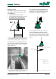
Appendix C Sensor mounting considerations General The ultrasonic sensor is characterized by a very narrow spread of the ultrasonic signal (3 ° - 7 ° depending on the type of sensor), which makes it possible to use the ultrasonic sensor under very tight conditions, i.e. in narrow wells or tanks. 80 % of the ultrasonic signal is concentrated within this area, which will give a sufficient echo that is sufficient in the far most cases.
Appendix In a tank / container Measurements Along a wall / other surface If the ultrasonic sensor is mounted for measurement of the level in a closed tank or container, it should measure through a pipe with a cutoff as shown below: The values in table 1 assume the ultrasonic signal is sent along a smooth surface like a wall or plane without any projections, joints, butts etc. If the surface is not smooth or has projections (i.e.
Appendix D Service menu Shuttle® has a service menu that gives access to settings that normally are not altered by the user and therefore are protected by a password. The service menu includes: - adjustment of the 4-20 mA output - adjustment of the temperature compensation - functional control of keyboard and display - relay check - changing of serial number and hardware/software numbers - self test function Refer to 'Shuttle® Service Manual' for further information of the functions in the service menu.
Appendix E Special menus Under certain circumstances it may be necessary to make adjustments and to make readings in the following special menus. It is recommended that only experienced users and MJK service technicians make alterations in these menus.
Appendix Bar graph read-out This function is used to select whether the bar graph should follow the analog output or the level read-out. Changes will not have influence on the relay settings. The bargraph follows the analog output. Note: If the mA settings are inverted (the level reference at 4 mA is set higher than the level reference at 20 mA), the bar graph will increase when the level decreases and vice versa. The bar graph follows the level read-out.
Appendix Active measuring range Shuttle®'s measuring range is normally set automatically to a distance corresponding to the ultrasonic sensor's distance to zero level + 45 cm. It may become necessary to decrease the active measuring range so it corresponds to the highest and lowest possible levels in the well /tank - especially if the ultrasonic sensor is mounted above a steel grating or an opening in a well cover.
Appendix Response time When the level changes, the display read-out will change accordingly with a pre-programmed delay. The response time is set to 100 mm/sec. from the factory, which means that an actual level change will not be shown in the display at a faster rate than 4 in per second. When measuring on turbulent surfaces, it may become necessary to increase the response time in order to obtain a more stable level measurement and also relay function.
Appendix Measuring method (application) Shuttle®'s high accuracy is partly obtained by controlling the strength of the ultrasonic pulse based on the strength of the received echo. (AP 1) When performing level measurements on foaming surfaces, granulate, sludge etc., the received echo is generally so weak that it would be better to let Shuttle® send out the ultrasonic pulses with full strength constantly.
Appendix mA output signal during system error This function determines how the mA output should act in case of a system error. System errors are most often caused by a weak or missing ultrasonic echo, but may also occur by failure of the ultrasonic sensor or failure in Shuttle®'s internal circuits. Select the desired condition with the arrow keys. The mA output will be locked on the last known value when a system error occurs. The mA output will give a fixed signal when a system error occurs.
Appendix Calibration of the level measurement If the distance of the ultrasonic sensor above the surface is known, it will be possible make a calibration of Shuttle®'s level read-out. The calibration will only have influence on the level read-out - not on relay setpoints for pump control, alarms etc. Note: Because of the built-in temperature compensation, it is important that the ultrasonic sensor has the same temperature as the surrounding air. Leave the sensor in the surrounding air for minimum 1 hour.
Appendix Offset level readout Shuttle® can display the levels with reference to a selectable offset level. This means that the normal zero level (when the tank is empty) is displaced up or down. Note: It is very important, that the distance from sensor to zero is set correctcly (see page 18), and that the active measuring range (see page 48) is set to a distance, that corresponds to the longest meaasuring distance that can occur.
Appendix Indication of echo quality This menu is used to indicate the strength of the received ultrasonic echo. If there are frequent system errors (see page 32), this function can be used to check if the ultrasonic echo is being weakened too much under the current working conditions - i.e. foam, waves etc. There are no specific limits indicating that the echo is too weak, since it depends highly on the current working conditions. Please contact MJK for advice.
Appendix Indication of signal amplification This menu is used to display the amplification level of the received ultrasonic echo. The function can give an indication og the strength of the received echo. If the amplification level is low (below. 20 dB), the echo strength is good and vice versa. A high amplification level (max. 50 dB) indicate that the ultrasonic echo is weak (foam or waves).
Appendix Indication of time period without echo This menu is used to display the longest time period during which Shuttle® has been missing an acceptable echo, and also how many days has passed since this occurred. The longest time period that Shuttle® has been missing an acceptable echo is displayed immediately. (In seconds.) Next, the number of days since the occurrence is displayed. The longest period with echo failure will be erased after 14 days. Shuttle® reverts to normal read-out.
Appendix Select factory settings All settings - except calibration of the level measurement - made after initial startup will be reset to factory settings with this function. The zero point setting will also be adjusted to the immediate level in the well / tank. Furthermore, the mA output is set to 4 mA at the current zero point and 20 mA at a level corresponding to a distance of 14 in from the ultrasonic sensor.
Appendix Access code To gain acces to the remaining menus, an access code is required. Press and hold 'Escape' at least for 5 seconds: The access code can now be selected: Use the arrow keys to select… (Standard access code is 100:) …and confirm with 'ENTER': All password protected menus can now be selected. Shuttle® will display the current level readings between menu selections. Shuttle® will revert to normal readout if: 1: the keyboard has not been used within 5 minutes. 2: 'Escape' is pressed.
Appendix Readout of version numbers Enter the access code (see page 58) and press'A': This menu is used to display version numbers for software and hardware and the unit's serial number. The hardware version number is displayed first: (Ex.: HW version 838003) Use the up-arrow to proceed. The software version number is displayed next: (Ex.: SW version 838014) Use the arrows to proceed. At last the Shuttle®'s serial number is displayed: (Ex.: serial no. 029400) Use the down-arrow to proceed.
Appendix Find zero level at next power-up Enter the access code (see page 58) and press 'B': This menu is used to force Shuttle® to start up with an automatic zero level setting at the next power-up. (See page 14.) The function is useful if ie. Shuttle® has been build into a control panel and has been set-up for a particular application. Shuttle® will then start up as it would when delivered from the factory, but the selected functions and setpoints will not be reset.
Appendix Fixed mA signal Enter the access code (see page 58) and press 'C'. This menu is used to make Shuttle® give out a constant 12 mA signal independent of the actual level readout. The function can be useful during fault finding on external equipment. Note: The output signal is constant 12 mA as long as this display is shown: Shuttle® is ready for a new selection of a password protected menu after pressing 'Enter'.
Appendix Investigative measurement intervals Enter the access code (see page 58) and press 'D': Shuttle® will normally perform an investigative measurement every 5 minutes in order to ensure that the unit has not locked on a false echo - i.e. a level signal which is not the actual level. If Shuttle® often locks onto solid objects within the normal interval, the interval for investigative measurements can be changed in this menu. The actual setting is shown immediately: (Value in seconds.
Appendix System alarm delay Enter the access code (see page 58) and press 'E': Shuttle® will give a system alarm (see page 32), if an acceptable echo has not been present within a preset period of time. If it is very important to know that the level measurement is valid at all times, the delay should eventually be decreased. The actual setting is shown immediately: (Value in seconds.
Appendix Averaging the level measurement Enter the access code (see page 58) and press 'F': When measuring on very turbulent liquid surfaces, it may be needed to average the level changes in order to gain a more steady level readout and level signal. This menu is used to set the time from a level change is measured and until the reading will be 99 % of the level change. See also page 49, 'Response time'. The actual setting is shown immediately: (Value in seconds.
Appendix Max. amplification level Enter the access code (see page 58) and press 'Shift' + 'A': If Shuttle® periodically has a system error and/or the level readout jumps to a high or low level during measuring in favourable conditions, it may be necessary to limit the amplification of the received echo. (See also page 66.) The effect from electrical noise can also be reduced or eliminated with this function. Note: A reduction in the amplification level may affect the maximum measuring range.
Appendix Min. level for accept of ultrasonic echo Enter the access code (see page 58) and press 'Shift' + 'B': If Shuttle® periodically has a system error and/or the level readout jumps to a high or low level during measuring in favourable conditions, it may be necessary to increase the limit for accept of the ultrasonic echo. (See also page 65.) On the contrary, it can be necessary to decrease the limit, if it is difficult to get a good echo, e.g. long measuring distances on difficult surfaces.
Appendix Sensitivity of the learning function Enter the access code (see page 58) and press 'Shift' + 'C': If Shuttle® periodically is locked on a false echo, even if the learning function has been activated (see page 28), it may be necessary to increase the sensitivity of the acoustic image that was stored in Shuttle ® during the learning process.
Appendix Changing the access code Enter the access code (see page 58) and press 'Shift' + 'D' The actual setting is shown immediately: Use the arrow keys to select a new access code: Confirm the new setting: Shuttle® is ready for a new selection of a password protected menu after pressing 'Enter'. (Re-entering the access code is not necessary if a menu selection is made within 5 minutes.) Press 'Escape' if no further password protected menu selections are needed … ...
Appendix F New sensor / changing sensor Shuttle® will be shipped and delivered from about July 1, 2007 with 1 of 4 different sensor types. If, at some other time, the sensor is to be replaced by another or a newer type, the following procedure can successfully be applied to re-configure the level transmitter. Technical specifications are located on pages 37 - 40. Open the choose sensor menu Press 'Esc' + 'E'.
Ultrasonic Level Transmitter and Sensor Liability MJK Automation A/S are liable to the common rules of Danish law on product liability, however, the liability is reduced to coverage of our public liability insurance of products. To the extent where nothing else follows in lines of invariable rules of law, we are not liable for loss of profits and working deficits or other indirect losses. Changes As our products are developed continuously, we reserve the right to make any alterations without prior notice.