401-862-4367 . mjmyachts@verizon.net November 2012 Dear 40z Owner: Congratulations on becoming Captain and Owner of the world’s best built and most fuel efficient yacht of its size. The enclosed copy of the 40z Owner’s Manual should further contribute to your enjoyment and proficiency afloat. This manual was created jointly with Zurn Yacht Design, Boston BoatWorks and MJM Yachts.
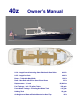
40z Owner’s Manual LOA - Length Overall Including Swim Platform & Bow Roller 44.3 ft. LOD - Length On Deck 40.0 ft Beam – Trailerable Max Width 12.0 ft. Draft – Max Draft with IPS or Stern Drives Down Displacement – ! Load 3.3 ft. 18,900 lbs. Fuel Tankage - In 2 175 gallon Tanks 350 gals. Fresh Water Tankage – Including Hot Water Tank 112 gals. Holding Tank Air Height over Water w/Radar Mounted on Hard Top 25 gals. 10 ft.
!"#$%&'(")*#$&"'% % % *"+,-% % % % 8&'%'9*!,)%% % % +,?&@'%A#$,'$% % % +,-&H,)I%+#$,% % % ),@&?$)#$&"'%'"L% % % % ,'@&',?% % % % *"+,-% % % % ?,)&#-%'"L% % % % H"-H"%:.
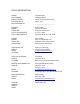
CE CERTIFICATION CERTIFICATE NO. AUTHORITY: ADDRESS: PHONE: WEBSITE: CLASSIFICATION: REGISTRATION #: CAPACITY PERSONS: PERSONS/GEAR: BBBW003 International Marine Certification Institute Rue Abbe Cuypers 3 B-1040 Bruxelles, Belgique +32-2-741-2418 www.imci.
TABLE OF CONTENTS CHAPTER 1 1.1 1.2 1.3 1.4 1.5 1.6 OPERATION GENERAL QUICK START GUIDE OPERATING PROCEDURES NAVIGATION TOWING HAULING OUT CHAPTER 2 2.1 2.2 2.3 2.4 SAFETY EQUIPMENT GENERAL FUEL SHUT-OFFS FIRE FIRST AID CHAPTER 7.0 7.1 7.2 7.3 7.4 CHAPTER 8 RAW WATER SYSTEM 8.1 GENERAL 8.2 ENGINE RAW WATER CHAPTER 9 9.1 9.2 9.3 9.4 CHAPTER 3 PROPULSION SYSTEM INTRO – TOP 10 REASONS of ENGINE FAILURE 3.1 GENERAL 3.2 COOLING 3.3 LUBRICATION 3.4 ZINCS & CORROSION 3.5 AIR INTAKES 3.
CHAPTER 1 1.1 OPERATION GENERAL This manual has been compiled to help you operate your yacht with safety and pleasure. It contains details of the yacht; the equipment supplied or fitted, its systems, and information on its operation and maintenance. Please read it carefully, and familiarize yourself with the yacht before using it.
CHAPTER 1 OPERATION Compass Heading & Calibration There are 3 heading references for navigation on the 40z: (1) The compass on the dash, (2) Autopilot digital compass, and (3) GPS COG (Course Over Ground). All of these headings should be within a degree or so of each other when underway. If not, it is recommended that differences be recorded on a deviation card after following the calibration method outlined below or better yet, employing the services of a compass adjuster.
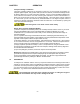
CHAPTER 2 2.1 SAFETY EQUIPMENT GENERAL Spend time reviewing where your safety equipment is and how it functions BEFORE you need it. Remember, the best way to protect yourself and others from accidents is to eliminate potential causes of accidents before they occur. Good seamanship and common sense go a long way in this endeavor. [See Figure 14.1] Here is a safety checklist derived in part from the USCG Vessel Check List.
CHAPTER 2 SAFETY EQUIPMENT First Aid Kit Not a place to scrimp. It is advisable to carry a good, comprehensive, and well-organized (by injury) marine first-aid kit with manual. We recommend that it be stored in the head and that everyone onboard be informed of its location.
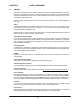
CHAPTER 3 PROPULSION SYSTEM INTRO - THE TOP 10 CAUSES OF ENGINE FAILURE It doesn’t happen often and if you’re familiar with the most common causes of engine failure you can cut down on the chances of a breakdown. As an introductory to this chapter, we want to familiarize you with this list of causes, compiled by Motorboating Magazine (February 2006). Here are the Top Ten to be aware of: 1.
CHAPTER 3 PROPULSION SYSTEM Prevention is easy: Visually inspect cooling hoses and squeeze them to be sure they retain shape and set. 6. CLOGGED INTAKE: Floating debris in the water is another culprit. Things like discarded plastic baggies, weeds, etc. can plug up the raw-water intake. You can avoid this problem by visually inspecting the strainer basket. When removing debris, be sure to properly replace the seal, otherwise the pump will lose suction.
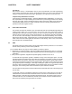
!"#$%&'()(*%+(,"#-',)%!')"%./(01%23#$%45-(0%6-(5% To run well, a diesel engine requires only clean fuel, clean lubricating oil, coolant, and lots of air. Below are ten important maintenance issues that diesel mechanics wish their customers knew: 1. Don’t baby the engine. Diesels don’t like to idle in neutral, or even in gear at low speeds; they do like to work hard under load. What’s cruising RPM? Generally, 75-80% of the maximum RPM.
7. Know how to trouble-shoot the cooling system. Since overheating is a common problem familiarize yourself with engine’s cooling systems: the raw water (sea-water) system, as well as the fresh water (internal circulating coolant) system. The most likely causes of overheating are: * Raw-water valve closed. * Raw-water through-hull blocked externally. Check for a plastic bag, or a clump of sea grass or other material, covering or plugging the inlet.
CHAPTER 3 3.0 PROPULSION SYSTEM PROPULSION SYSTEM 3.1 GENERAL Your 40z is propelled by twin Volvo diesel 370 HP D6 engines with 24 overhead valves, turning (via IPS transmission) forward facing duo-prop propellers. The dual-lever electronic control acts as a combination throttle and gear selector. Care should be taken when shifting. Always allow the transmission to engage the new gear before throttling up. If the two levers are set to within 200 RPM of one another, they will automatically synchronize.
PROPULSION SYSTEM CHAPTER 3 3.2 COOLING Your engine passes seawater (raw water) through an intake in the IPS drive unit under the hull through a heat exchanger where it cools the engine’s coolant. This coolant is circulated through the engine and returns to the heat exchanger. For the engine to keep cool, it must have an adequate supply of raw water and coolant. Periodically check to be sure it’s clean and check the coolant level by opening the caps on top of the engine.
CHAPTER 3 PROPULSION SYSTEM 3.5ENGINE AIR INTAKES Diesel engines use a large quantity of air for combustion. The engine of the 40z gets this air thru grills under the cockpit coaming, both port and starboard. Be sure that these aren’t blocked with gear on deck when underway. 3.6 ENGINE CONTROL/DISPLAY PANEL The EVC Control Panel allows the operator to perform settings and choose information displayed on the engine LCD Display screen below. See Volvo Operator’s Manual for settings and options.
PROPULSION SYSTEM 3.7 ENGINE CONTROL LEVERS There 5 positions (front to back). FORWARD IDLE FORWARD NEUTRAL IDLE REVERSE REVERSE The port and starboard engine RPMs will synchronize automatically when within 200 RPM of each other. Emergency Shifting If a fault occurs which prevents electronic gear shifting with the control levers; it is possible to shift manually using the procedure outlined on page 56-57 of the VPOM. SUDDEN MOVEMENT HAZARD This control lever governs both throttle and shifting functions.
CHAPTER 3 PROPULSION SYSTEM 3.9 ALARM DISPLAY When the ignition key is first turned ON to position I, you may hear an audible alarm signal and see a “Stop Sign” appear on the Display, indicating that the diagnostic function has registered a malfunction. Please refer to Volvo Operator’s Manual chapters for detailed information about FAULTS and recommended action starting on page 40 of the VPOM. 3.10 STOPPING Put both engine controls in NEUTRAL.
CHAPTER 4 4.1 STEERING CONTROL SYSTEM STEERING SYSTEM The 40z has an integrated, electronically controlled power steering system which through electric motors rotate the two IPS pod drives below the hull. When running, the 40z is steered as with outboards or sterndrives. Thrust of the propellers is directed more immediately and precisely from side to side through a 26° arc to steer the boat.... rather than bouncing the prop wash from a conventional straight shaft propulsion unit off a rudder.
CHAPTER 4 STEERING CONTROL SYSTEM spin the boat completely around on its own axis. Pretty simple Takes some practice until it becomes completely intuitive. Joystick Calibration When moving the boat sideways if it seems that the bow or stern moves more than the other see page 109 of the Volvo Penta Operator’s Manual to make adjustments. 4.3 HELM STATION NOTE: Panel Layout may vary between boats. The helm station console is where most of the operational controls of the boat are located.
CHAPTER 4 4.4 STEERING CONTROL SYSTEM CONSOLE SWITCH PANEL With the exception of the Anchor Washdown which is activated along with the “Windlass” breaker (and must have the “Water Pressure” switch ON as does the washer function of the “Wiper” switch) functions of this panel on the console are activated by turning on their respective breaker switches on the DC Electrical Panel in the main saloon. Functions of the panel rocker switches are described below the corresponding switch: Press to Sound HORN 4.
CHAPTER 4 STEERING CONTROL SYSTEM could cause the boat to attempt to roll over, particularly in a turn, due to the angle of IPS drives under the hull. Caution is advised. 4.6 AUTOPILOT p70r The Navigtion Electronics breaker on the DC panel must be ON for the autopilot to function. Check the autopilot display and note the rudder angle indicator which helps in maneuvering the boat. When the compass heading is displayed on the autopilot it is operational and can be activated by pushing AUTO.
CHAPTER 4 STEERING CONTROL SYSTEM . If the wiper’s washer system is to be used in sub-freezing temperatures, a separate system must be installed which utilizes anti-freeze. 4.8 SPOTLIGHT The spotlight is mounted properly on the bowrail where reflection off the foredeck and stainless fittings is eliminated. To activate, the “searchlight” breaker on the DC panel must be ON and the “S” for spot or “F” for floodlight must be depressed. The center button with the arrows controls the direction.
CHAPTER 5 5.0 FUEL SYSTEM GENERAL It is important to understand the fuel system aboard your boat. Diesel fuel is different than gasoline. In most respects it is safer, however precautions need to be taken to maintain the safety of your boat. Please study the safety precautions in the NMMA publication “Sportfish, Cruisers, Yachts – Owner’s Manual.” Diesel engines need to intake more fuel than they burn, and so they differ from gasoline engines in that they return excess fuel to the tank.
CHAPTER 5 5.3 FUEL SYSTEM RACOR PRIMARY FUEL FILTERS Racor Filters are your first line of defense against bad fuel and are installed just after the shut-off valves in the fuel lines, inside the Systems Room, on either side bulkhead just forward of the generator. Check these filters regularly for any accumulation of water or contamination. Water will appear as a dirty gray, cloudy substance in the clear bowl. You should be able to see thru the pink fuel in the bowl at all times.
CHAPTER 5 FUEL SYSTEM Propulsion Systems. The NMPG and Range numbers will also vary depending on engines installed and the relative efficiency of the propulsion unit. It’s anticipated that the standard sterndrives and/or lighter Volvo D4 or the Cummins QSD4.2 engines will improve the efficiency by a tenth or two from those shown below.
MJM FUEL CONSUMPTION LOG !"#$ %&'"#(&) ,-.+ $)*+ /0123+ *"%.+ ,-. %".#+ 56+4(%% 4(%% *7, '&88$)#.
CHAPTER 6 6.0 ELECTRICAL SYSTEM GENERAL The 40z’s electrical system may be more advanced than what you are accustomed to. It combines DC and AC power in several ways. Most of the electrical components on your boat use DC power. 12 volt DC power is stored in two 8D House Batteries and two 31G Start Batteries, totaling 700 Ampere Hours of capacity.
CHAPTER 6 ELECTRICAL SYSTEM DC Breaker Panel This custom MJM panel includes s digital readout that will show voltage and amperage drain on top. The main house battery and genset breaker switches are in the upper right. The breaker switches for all the 12v DC equipment on the boat are clearly labeled and some spares are available for later installations. AC Breaker Panels The main AC Engine battery breakers are located at the top right over AC Panel #2.
CHAPTER 6 ELECTRICAL SYSTEM Charging The HOUSE battery switch can be switched OFF when the boat is not used, and the batteries will still accept a charge from 110V Shorepower through the battery charger. Leave “Inverter/Charger” breaker ON on AC Panel 1. Disconnecting shore power with INVERT left ON will cause discharge of the house battery bank.
CHAPTER 6 ELECTRICAL SYSTEM Hot Water If a second shore-power receptacle is not available and you have not operated the boat recently; there won’t be any hot water from the engine’s heat exchanger. Simply turn ON the Transfer switch of Shore 2, flick the hot water breaker on, wait 15 minutes and your shower will be ready.
CHAPTER 6 ELECTRICAL SYSTEM Check to see that AC volts are now reading on the digital meter over AC Panel 2 by throwing the toggle switch between the digital displays to “Shore 2”. TURN BREAKERS ON for the items you wish to operate. Note: if the generator starts, but no AC voltage is seen at the panel, check first that the selector switches (sliding interlocks) at the top of the AC panel are ON.
CHAPTER 6 6.4 ELECTRICAL SYSTEM MASTERVOLT INVERTER/CHARGER Mastervolt PN 37014005 12/4000-200A Mass Combi Inverter Charger is fully automatic. Under normal circumstances there is no need for adjustment or operation besides switching on and off. The Mass Inverter Charger Control (MICC), shown at right in the “Charge” mode, is a digital remote panel switches on and off the Mass Combi unit but is a battery consumption meter.
CHAPTER 6 ELECTRICAL SYSTEM DO NOT LEAVE THE INVERT SWITCH “ON” ON THE MICC PANEL ALONG WITH THE INVERTER/CHARGE SWITCH “ON” ON THE AC PANEL IF YOU ARE NOT INVERTING AS THIS MAY DRAW 10-12 AMPS EVEN IF NO AC DEVICE IS TURNED ON. OR, YOU MAY END UP WITH DEAD BATTERIES (All of them if the Parallel Switch is “ON” too.) Charging Push CHARGER on the MICC panel to activate the charger when SHORE POWER is applied to AC Shore 1 or when the GENERATOR is on.
CHAPTER 6 ELECTRICAL SYSTEM Sea Fire Supply 10 amp AGC House Switch Supply 15 amp AGC House Remote Supply 5 amp AGC Start 1 Switch Supply 15 amp AGC Start 1 Remote Supply 10 amp AGC Start 2 Switch Supply 15 amp AGC Start 2 Remote Supply 10 amp AGC Generator Switch Supply 15 amp AGC Generator Remote Supply 5 amp AGC Combiner 1 Negative 15 amp AGC Combiner 2 Negative 15 amp AGC Engine Room Blower Engine Room Blower VacuFlush 15 amp 15 amp 3 amp AGC AGC AGC House Bus at th
CHAPTER 7 7.0 FRESHWATER SYSTEM GENERAL The 40z incorporates a pressurized freshwater system from either of two sources (1) a single 100-gallon tank under the main saloon sole that supplies a pump which maintains a constant pressure in the system, or (2) a dock hose inlet located to port in the cockpit as shown at right. When connected, dock water and pressure is used directly by all outlets in the boat... by passing the freshwater pump and water tank.
CHAPTER 7 7.4 FRESHWATER SYSTEM GENERAL ECOLOGY SEAGULL WATER PURIFIER [See also Seagull owner’s manual] The galley is fitted with the best available water purifier in the world. It is used on 85 airlines. This purifier has a cartridge (in stainless pressure vessel under sink) that should be replaced annually or when reduced water flow indicates that it has become plugged with sediment. It is best to clear the pressure water system of any winter anti-freeze before running water through the cartridge.
CHAPTER 8 8.1 RAW WATER SYSTEM GENERAL Raw water (seawater) is used to cool the engine and the generator. It is also used in the washdown and air-conditioning options. Wherever raw water enters the boat, it does so through a seacock, which is a valved thru-hull penetration with double-clamped hoses. 8.2 ENGINE RAW WATER The engine intakes are through the drives as seen in the chapter on propulsion. The generator (if fitted) use separate seacocks and strainers.
CHAPTER 9 9.1 GRAY WATER SYSTEM GENERAL Gray water is liquid that can legally be pumped overboard, generally from sink drains, shower drains, and bilges. Your boat also directs deck run-off to of all gray water through common drains (port & starboard) in the transom. 9.2 GRAY WATER SUMPS There are two gray water sump boxes aboard your boat located (a) in the storage compartment under the hatch in the cabin sole between the shower and head and (b) below the bottom companionway step.
CHAPTER 10 EXTERIOR EQUIPMENT 10.1 GENERAL Although all the exterior equipment on your boat was selected with marine service in mind, it is helpful to rinse the boat with freshwater after exposure to saltwater. 10.2 ANCHOR WINDLASS Refer to the manual that came with your windlass for specific operating instructions. The windlass draws power from the engine start battery.
CHAPTER 10 10.4 EXTERIOR EQUIPMENT PRIVACY/SUNSCREEN CURTAINS (OPTION) Fine white mesh allows you to see out but makes it difficult to see in as demonstrated below. When installed at night, these curtains convert the Pilothouse to an additional stateroom. The 8 Curtain set comes rolled up in its own carry bag. The aft and windshield curtains attach by Velcro inside.
CHAPTER 10 10.6 EXTERIOR EQUIPMENT STIDD SEAT POSITIONS The two piloting seats are designed to swivel around and be lowered for a more sociable setting in the pilothouse. Be careful to slide the seats fully forward prior to swiveling so the seat is not jammed into the pilothouse sidewalls. Optional “Wide” Stidd Seats are available that function in the same manner. 10.
CHAPTER 11 INTERIOR EQUIPMENT 11.1 MARINE VACUFLUSH HEAD SYSTEM Waste discharge regulations vary by location. Check with local authorities. The waste system aboard your boat employs freshwater and a vacuum generator. The freshwater pump breaker and Vacuflush breaker must both be on (DC panel) for the system to work. Further controls are located on a panel in the head (shown). Refer to the manufacturer’s manual for more details.
CHAPTER 11 INTERIOR EQUIPMENT 11.4 SHARP GRILL 2 CONVECTION MICROWAVE This unit offers several cooking modes which maybe operated without shorepower by utilizing the inverter for AC power and turning ON the MICROWAVE switch on AC Panel #1. Please refer to the Sharp Users Manual for operating instructions and precautions. The manual is stored inside the oven when the boat is initially delivered. 11.
CHAPTER 11 INTERIOR EQUIPMENT 11.8 SIRIUS SATELLITE RADIO ACTIVATION (Optional) To activate Sirius Satellite Radio services on the Clarion CMD-5, you will need the serial number: (1) Push the “MENU” button. (2) Using the up and down scroll to “SID DISP”, then press “ENTER”. (3) The first 6 digits of the serial number will be displayed.
CHAPTER 11 11.10 INTERIOR EQUIPMENT KVH M3 SATELLITE TV RECEIVER (Option) To activate the receiver, turn ON the breaker labeled “Satellite Dish” on the DC Panel. Then be sure that the KVH dish control and receiver are turned on in the Entertainment Center. Follow the instructions in the KVH Owner’s Manual to initiate subscription and enjoy television reception aboard the boat. Either DISH Network or Direct TV has been selected prior to installation.
CHAPTER 11 INTERIOR EQUIPMENT (3) Run the radar dome harness through the hole in the front of the strut, just behind where the radar dome will sit. See Pic 2 above. (4) After installing the radar on it’s platform and running the harness inside the radar dome you will need to remove 5 screws from the top of the metal box (the cover will than hinge to the side-- see Pic 3) giving you access to the radar connections). You will have 2 red wires, 2 black wires and a plug with 7 smaller wires attached to it.
CHAPTER 11 INTERIOR EQUIPMENT (7) Connect the RG6 cable to the 90º connector, located in the bottom of the KVH dome. Once this is done, mount the dome on the strut with the bolts provided.
CHAPTER 12 ROUTINE MAINTENANCE 12.1 SCHEDULE Refer to the following chart for an approximation of routine maintenance actions. Refer to the Volvo-Penta IPS Operator’ Manual, page 62-64, for more complete instructions on each item. Perform all maintenance once a year even if hour levels have not been reached. Some of the items you may choose to leave to professionals, but many you can do yourself.
CHAPTER 12 ROUTINE MAINTENANCE GRAY WATER SYSTEM Sumps Annually Automatic Bilge Pumps (3) Daily Check Manual Bilge Pump Monthly Bilge Area Daily Check In Main Cabin Floor Hatch & Systems Room Test with manual switch Check operation Inspect and clean as needed ELECTRICAL SYSTEM Batteries Monthly House & Engine Batteries Daily Check Connections Annually Transom & Drive Zincs Quarterly Remove Lids, check for loose cables, clean Voltage Inspect all connections Inspect and replace if necessary MISCELLANEOU
CHAPTER 13 SEASONAL MAINTENANCE 13.1 START OF SEASON [commissioning] 13.2 END OF SEASON Most facilities will not require additional information before hauling the boat with a Travelift or crane, but if this is the case, use the included Lifting Diagram Figure 14.10. The end of the season is a good time to have the bottom power-washed and to check all thruhulls and seacocks for growth. Careful inspection of all underwater hardware at this point may avoid a potential problem in the future.
14.
14.
14.
14.
14.
FIGURE 14.
TRAILER LOADING CHECKLIST 1. Place all cockpit & pilothouse cushions below on island berth. 2. Remove canvas from Bimini, detach aft legs and hinge the main hoop forward against the hardtop. Secure the short legs, pad the main hoop where it touches the hardtop (AC hose) secure the hoop to handrails with fender whips. 3. Hinge down VHF antenna and reverse tape it to starboard handrail. 4. Hinge down running light and tighten. 5. Remove any KVH or FLIR tower and seal hardtop openings and wire connections.
CHAPTER 15 BOSTON BOATWORKS LIMITED WARRANTY Manufacturer’s Sole and Limited Warranty for Pleasure craft A. General. This document sets forth the sole and limited warranty, which Boston BoatWorks (“The Manufacturer”) is giving you in connection with the “Vessel” which you are acquiring. It is the only warranty being given by the Manufacturer and should be reviewed carefully together with manuals and other instructional material provided by the Manufacturer before you take delivery of the Vessel. B.
Manufacturer, and perform maintenance to the Vessel as recommended in the Manuals and as required by periodic inspections by an Authorized Dealer or Service Center. H. Warranty Claims. To make a claim under this warranty you must do the following a. Report the defect to the Manufacturer or Authorized Dealer within thirty (30) days of discovering it, and when possible prior to incurring any expense, identifying the Vessel and submitting photographs (email digital preferred). b.
BOSTON BOATWORKS Pre-Approval for Warranty Please Fax Claim to: (617) 561-9222 Date_______________________ Boat Model_______________Boat Name_________________________Hull #______________ Dealer__________________________Contact Person__________________________________ Phones___________________Fax___________________ Email_________________________ Description of Problem: _________________________________________________________ _____________________________________________________________________________ _
Warranty Claim Application Form Boston BoatWorks, LLC 256 Marginal Street, East Boston MA 02128 Phone: (617) 561-9111 Fax: (617)561-9222 Date:______________ Boats Name:______________________ 40z Hull # ________________ Dealer/Service_______________________ Boat Owner:_________________________ Address: ____________________________ Address:____________________________ ___________________________________ ___________________________________ Phone:_____________________________ Phone # ____________________
CHAPTER 16 QUICK START GUIDE 1 - Disconnect Shore-side Connections To disconnect shore power cords, turn off all AC loads on the boat and make sure the main AC breakers on the AC panel (the double breakers) are all OFF. Then disconnect the cord at the dock end first. Disconnect the cord at the boat and close the shore power inlet cover. Ditto for any phone/cable TV lines and dock water inlet.. 2 - Set Battery Switches The Engine battery selector switches are on the AC electrical panel.
6 - Check DC Panel Check the DC panel to insure that the house bank has a reasonable charge (12.2V or greater). If there is any problem, now is the time to learn of it. Make sure the DC MAIN breaker is ON, as well as any other circuits that you might need in the course of your trip. If you need the searchlight in a hurry, for instance, it’s better to have the breaker already on. 7 - Turn ON Navigation Instruments Turn on TRIM TABS, NAV INSTRUMENTS, VHF, HORN, WIPERS.