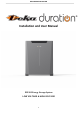
DEKA DURATION DD5300 Installation and User Manual DD5300 Energy Storage System LOW VOLTAGE & HIGH VOLTAGE 1
DEKA DURATION DD5300 ATTENTION: The battery could explode and/or be severely damaged if dropped or crushed. ATTENTION: Appropriate mechanical lifting equipment must be used since the Battery Module weighs 126.3 lb (57.3 kg). ATTENTION: The battery may explode if exposed to open flames or other extreme sources of heat. ATTENTION: The battery terminals must be disconnected before commencing any work on the battery. ATTENTION: This battery can accumulate parasite current.
DEKA DURATION DD5300 Contents Statement: ....................................................................................................................................... 6 Preface: ........................................................................................................................................... 6 Declaration: ..................................................................................................................................... 6 System Design ..................
DEKA DURATION DD5300 1.3.3 Stack Mount .................................................................................................................................................................... 23 1.4 Battery Terminal Function Definition.......................................................................................................... 25 1.5 Out of the Box Pre-Operational Check ........................................................................................................
DEKA DURATION DD5300 2.9.8 Conceptual Diagram between Master Modules of multiple clusters..................................................................................... 57 2.10 Cluster Configuration Accessories ............................................................................................................ 58 2.10.1 Single Cluster Configuration Kit ....................................................................................................................................... 58 2.
DEKA DURATION DD5300 Statement: The information and guidance contained in this manual is related to the DEKA DD5300 Stackable model of battery. This manual contains two sections: Section 2 is for LOW VOLTAGE APPLICATION Section 3 is for HIGH VOLTAGE APPLICATION In case of product upgrades or other reasons, this document will be adjusted accordingly.
DEKA DURATION DD5300 System Design System Design is the process of defining the architecture, components, modules, interfaces and load data for a system to satisfy specified requirements. For a solar energy system, these components are the PV modules, inverter/charge controller & batteries, as well as the different interfaces of those components. Battery Operation There are several factors that affect the operation of the battery that could impact its ability to deliver capacity and life expectancy.
DEKA DURATION DD5300 Product Overview The Deka Duration DD5300 is a Stackable Battery Module with a DUAL VOLTAGE module that can be used in a Low Voltage configuration or in a High Voltage configuration. For LOW VOLTAGE (48.5-58.4 Vdc)* Configuration Refer to Section 2 For HIGH VOLTAGE (200-934.4 Vdc)* Configuration Refer to Section 3 *Voltage ranges are estimates only as they always depend on interactions with other devices and ambient conditions.
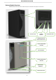
DEKA DURATION DD5300 Battery Module Overview INFORMATION provides tips that are valuable for optimum installation and operation of the product.
DEKA DURATION DD5300 ATTENTION: THE BATTERY IS DUAL VOLTAGE – IT CAN BE INSTALLED IN EITHER A HIGH VOLTAGE CONFIGURATION OR A LOW VOLTAGE CONFIGURATION, BUT NEVER BOTH AT THE SAME TIME. BE AWARE OF THE DIFFERENT CONNECTION METHODS AND THE SPECIFIC USE OF THE TERMINAL CONNECTORS.
DEKA DURATION DD5300 Safety Warnings and Notifications Installation environment requirements: The Deka Duration DD5300 Stackable Battery Module is designed for household/commercial purposes. For installation, it must be installed in a location complying with IP20 (IP 55 or 65 are available on request). Installations in locations that do not comply with IP20 may cause failure and/or damage to the product, in which case the product warranty will become void.
DEKA DURATION DD5300 Warning Statements Lithium Iron Phosphate (LiFEP04) Battery or Cell DANGER Hazard Statement The materials contained in this product may only represent a hazard if the integrity of the cell or battery is compromised; physically, thermally, or electrically abused. The below are the hazards anticipated under those conditions: Causes skin irritation. Causes serious eye irritation. May cause an allergic skin reaction.
DEKA DURATION DD5300 General Preparation Before Installation: Ensure that all the modules are turned OFF. Battery installation location should be at least 20m away from sources of heat, sparks or other sources of extreme temperature. Battery connecting cables shall be as short as possible to prevent excessive voltage drops. Batteries with different capacity, different type/model or design or from different manufacturers shall not be connected together. 1.
DEKA DURATION DD5300 ATTENTION: STACKABLE INSTALLATION INFORMATION The stack configuration shall be concluded by interlocking the modules by using the module feet as shown below: Use the two screws to fix the feet across the modules The screw holes are on the side of the battery Install the feet across the modules 14
DEKA DURATION DD5300 When operating in stack mode, remove the upper (trapezoidal) front part from the Battery Module to allow the cables to pass through. The front plate must be reinstalled to protect the cables after the installation is complete. REMOVE WHEN OPERATING IN STACKABLE MODE CABLES PASSAGE ATTENTION: The DD5300 Battery Module has two terminals for connecting the power supply. The installer must pay the utmost attention to the respective functions.
DEKA DURATION DD5300 SECTION 1 - STORAGE & PRE-OPERATIONAL PROCEDURES 1.1 Storage - Transportation – Removing / Relocation of Batteries ✓ This Battery is considered DANGEROUS GOODS by the United Nations and must be treated accordingly. ✓ Each box comes from the factory with the below labels: ✓ This battery can only be transported and stored with the original approved carton box, Certified as per UN CLASS 9 Y80. ✓ This Battery must be stored in its original carton box in a dry and cool place.
DEKA DURATION DD5300 The installer approaching this battery model for the first time must understand the use and operation of its accessories. The DD5300 Battery Module can be equipped with an auxiliary combiner such as: DD21001 HUB for Low Voltage configurations up to 105 batteries (7-Clusters x 15-Modules) DD21002 HV BOX device for High Voltage configurations up to 144 batteries (9-Clusters x 16-Modules).
DEKA DURATION DD5300 1.2 Module Unpacking and Handling The battery is always delivered in WALL mode, and it is therefore necessary for the installer to make simple changes to install the STACK kit. Below are the installation phases. ATTENTION: The battery must be lifted by four persons, using the four handles. Two handles are built in and the other two are provided as temporary handles to be used as shown below.
DEKA DURATION DD5300 1.2.1 Package Information and System Configuration List The battery box is packed in cartons with accessories. Upon receipt, review the configuration list carefully to make sure that the battery box and accessories are received in the correct quantities and type, and visually inspect to ensure that they are free from damage. Refer to Section 2.1.3 for Low Voltage packing list and to Section 3.1.3 for High Voltage packing list.
DEKA DURATION DD5300 ATTENTION: The Battery Module weighs 126.3 lb (57.3 kg) and must be installed with the help of a mechanical lift, and/or with at least two people equipped with suitable suction cups for mechanical lifting or lifting straps. STEP 1A 100/120 cm suggested height The Bracket must be installed on a flat and vertical wall. The steel bracket must be flush to the wall without any empty spaces between the wall surface and the back side of the bracket.
DEKA DURATION DD5300 Step 2A: In case of multiple module installation, make sure to respect the distance between the modules and the ceiling. Min 30 cm 25 cm 25 cm 25 cm 25 cm 25 cm Example of a Floor or Wall Mounted battery cluster connected with power cables and data cables. Note: In a single cluster configuration, there is no need to set the DIP switch on the master battery. All DIP switches should be set to OFF. The single cluster will self-configure.
DEKA DURATION DD5300 Examples of a Floor or Wall Mounted battery cluster.
DEKA DURATION DD5300 1.3.3 Stack Mount ATTENTION: The Battery Module weighs 126.3 lb (57.3 kg) and must be installed with the help of a mechanical lift, and/or with at least two people equipped with suitable suction cups for mechanical lifting or lifting straps. As previously stated in this manual, the DD5300 Battery Module comes as standard in wall mount configuration. To install in the Stackable configuration, the screws on the back of the battery module must be removed. 1.
DEKA DURATION DD5300 ATTENTION: Before stacking the batteries, the installer must check the maximum permissible floor load. It is recommended that the installer obtains approval from a civil engineer. For vertical ground mounting, the support surface of the Battery Module is distributed on 4 insulated supports (rubber pads), 10 x 4 cm each. Make sure to install a distribution plate or make a proper foundation to support the weight.
DEKA DURATION DD5300 1.
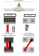
DEKA DURATION DD5300 1.5 Out of the Box Pre-Operational Check RUN BUTTON POWER SWITCH OPERATOR PORT Attention: Do not make any connection to the Battery Module until you have thoroughly read and understood this entire manual. The Run Button and the Power Switch are located on the right side of the Battery Module as shown above. The Power Switch is a RED mechanical ON/OFF switch that enables/disables the power supply of the BMS.
DEKA DURATION DD5300 SECTION 2 - LOW VOLTAGE CONFIGURATION 2.1 Product Introduction The Deka Duration DD5300 Battery Modules can be used as an on-grid or off-grid energy storage system. It is not recommended to use this product for any purpose other than the intended purpose as described in this document. Use of this product other than as described in this document will nullify the product warranty. The substitution of any components of this Battery Module will nullify the product warranty.
DEKA DURATION DD5300 Product Identification and labels The nameplate label describes the product parameters and is attached to the product. For details, please refer to the nameplate label of the product. For safety reasons, the installer must have a thorough understanding of the contents of this manual before installing the product.
DEKA DURATION DD5300 2.1.2 Accessory List (Standard Kit 120A Single Module LV) The Battery Module is packed in a carton together with standard accessories. When unpacking the Battery Module, be sure to check that the Battery Module and accessories are free from damage and that the correct quantities of each component are included within the carton. The following list of components can be used as a checklist when unpacking the individual Battery Module and battery kits.
DEKA DURATION DD5300 2.1.3 Necessary Installation Tools Multimeter + Current clamp Insulated Screwdriver Set Insulated Allen Key Set from 2 mm to 8 mm Drill + Hammer RS232/USB + Screw Terminal (insulated) Electrician Scissors Insulated Torque Wrench Set Lifting Strap + Mechanical Lifter 2.1.
DEKA DURATION DD5300 2.2 Low Voltage Module Wiring and Set Up 2.2.1 Battery Connection Terminals CAUTION: The LV fuse is contained in the left portion of the Battery Module as shown above. The access to the fuse is restricted to authorized Deka Duration service personnel and the protection lid cannot be opened by anyone else. The same applies to the HV fuse. 2.2.
DEKA DURATION DD5300 2.3 Low Voltage DIP Switch Settings ATTENTION: ALWAYS CONFIGURE THE DIP SWITCH SETTINGS BEFORE CONNECTING ANY POWER CABLES TO THE BATTERY TERMINALS B+ AND B-. WHEN CHANGES HAVE BEEN MADE TO DIP SWITCH SETTINGS, THE BATTERIES MUST ALWAYS BE RESTARTED FOR THE CHANGES TO TAKE EFFECT. POWER CABLE CONNECTIONS MUST BE MADE IN STRICT ACCORDANCE WITH THE INSTRUCTIONS IN THIS MANUAL. INCORRECT POWER CONNECTIONS CAN DAMAGE THE BATTERY MODULE AND CAUSE INJURIES.
DEKA DURATION DD5300 2.3.1 LOW VOLTAGE PARALLEL CONFIGURATION The DIP switch must be set as follows to allow a single Battery Module to communicate with an inverter using CAN communications: WHEN THE INVERTER HAS A CANBUS COMMUNICATION PORT, SWITCH #7 OF THE MASTER BATTERY MUST ALWAYS BE SET TO “ON.
DEKA DURATION DD5300 Name Meaning Function or Indication Status POWER SWITCH On/Off Button Switches the Battery Module on and off. RUN BUTTON Module Correct Operation When the Battery Module is running normally, indicator light will be STEADY GREEN. LOW BATTERY Low SOC When the battery SoC is low (SoC<0-5%) the RUN Button will blink in a GREEN color at 1 second intervals. The RUN Button will stop blinking and turn STEADY GREEN when the battery is in charging mode and the SoC reaches 10%.
DEKA DURATION DD5300 Attention: All drawings are for reference only. Always refer to the physical product as the standard. If the manual does not match the physical product, stop all actions, remove any connections, and store the batteries in a safe place. Call your Deka Duration technical service representative for assistance. 2.5 Low Voltage Parallel Set Up Overview DD5300 can be connected in parallel up to 15 modules, this process requires a full knowledge of the product.
DEKA DURATION DD5300 CAN to Inverter To start up the system just press the Master Run Button CAN PORT 2A MASTER Port RS485B Port RS485A SUB 1 Port RS485B Port RS485A SUB 2 Port RS485B Port RS485A 15th / or Last Module 2.5.
DEKA DURATION DD5300 STEP 2 AUTO WAKE-UP PROCESS (Pressing the RUN BUTTON ) Once all the connections have been checked, it is possible to start the Battery Module by enabling the automatic wake-up process. Press the RUN button of the MASTER battery, the RUN BUTTON will Blink and will wake-up all the SUB batteries connected. This process might take around 2-3 seconds per battery (Do not turn on the SUB manually as the automatic process will assign a battery ID in sequence). PRESS THE RUN BUTTON 2 Sec.
DEKA DURATION DD5300 2.5.2 Single Cluster DIP and DATA Connection The DIP SWITCH setting for the SINGLE CLUSTER LV mode has an automatic function that assigns the single module ID in cascade. It is mandatory to connect each module in Daisy Chain connection starting from the RS485B PORT of the master unit. The DIP sequence for the LV single cluster must be on every module that composes the cluster.
DEKA DURATION DD5300 2.5.3 Parallel Battery Wiring Connections ATTENTION: POWER CABLE CONNECTIONS MUST BE MADE IN STRICT ACCORDANCE WITH THE INSTRUCTIONS IN THIS MANUAL. INCORRECT POWER CONNECTIONS CAN DAMAGE THE BATTERY MODULE AND CAUSE INJURIES. 14 Nm (10.
DEKA DURATION DD5300 2.5.4 Low Voltage Single Stack Power and Data Connections (15-Modules Maximum) Proceed with the physical installation of the desired quantity and configuration of the Battery Modules, following the installation sequences and guidelines as described in Section 1 and Section 2 of this manual. Connect the power cables as indicated below, making sure that the batteries are OFF (check the button LED on the bottom) and always measure the terminals with a multimeter to check for ZERO VOLTS.
DEKA DURATION DD5300 Information: Connect the cables according to the installation requirements, always paying attention to minimize the length of the cables to avoid voltage drops. Attention: To ensure safety and stability of the cluster always connect the Battery Modules using the feet. 1st Attention: Install the stackable flat front cover plate to protect the bus bar and cables BEFORE TURNING ON 15th or Last Battery Modules installed correctly, see image below.
DEKA DURATION DD5300 2.5.5 LED Bar Indications The LED bar is located on the front of the battery and is to be used as a visual indication. OVER/UNDER TEMPERATURE START UP 12- LED BAR Check.
DEKA DURATION DD5300 2.6 Stand Alone Battery Front Panel Control 2.6.1 Start Battery Press the Run Button for 2-seconds. The GREEN RUN light should come on. The Battery Module has been activated normally. 2.6.2 Shut Down Battery Press and hold the RUN Button for 5-seconds. The GREEN RUN light should go off. The Battery Module has been shut down normally. 2.6.3 Low Battery – Force Charge Prerequisite: The VOLTAGE between the battery B + and B- terminals is ZERO and the PANEL LIGHTS ARE OFF.
DEKA DURATION DD5300 2.7.2 Shutdown of Parallel Batteries Press and hold the Master Run Button for 5-seconds. The GREEN RUN light should go off immediately. The GREEN RUN lights on the sub batteries will not be extinguished immediately. The RED FAULT lights on the sub batteries’ FRONT LED bars will start flashing after ten seconds and the GREEN RUN lights will remain on. After one minute the RED Fault lights on the FRONT LED bars and the GREEN RUN Button lights on all sub batteries will go off.
DEKA DURATION DD5300 2.7.3 LV Direct Parallel Connection WITHOUT Certified Inverter BMS Communication (Open-Loop) It is recommended to always use an inverter equipped with CAN communication as listed in this manual, however any inverter can be used with Deka Duration batteries by setting the voltage and current values according to the table below.
DEKA DURATION DD5300 2.7.4 LV Direct Parallel Connection WITH Certified Inverter BMS Communication (Closed-Loop) Note that for installations WITH certified Inverter BMS Communications the maximum number of battery modules per installation is limited to seven clusters of fifteen Battery Modules per cluster. The DD21001 Low Voltage Hub must be used when the installation has more than one cluster.
DEKA DURATION DD5300 2.8 Power Connection of a Single Cluster -Double BUS BARATTENTION: Both ends of the cluster must be connected with two output cables 50 mm2. Cables length shall not exceed 250cm. The suggested output cable is composed of two sets of 50 mm2 each. ATTENTION: The terminal block pole can support a 19mm width Cable Lug.
DEKA DURATION DD5300 Cable size verification for a cluster composed by 5 or more Battery Modules connected to the inverter with 2 sets of cables (50mm² each) for a total of 100 mm² each terminal (positive and negative). Numbers of Modules 1 2 3 4 5 6 7 8 9 10 11 12 13 14 15 C-Rate 1 0.98 0.96 0.94 0.92 0.9 0.88 0.86 0.84 0.82 0.8 0.78 0.76 0.74 0.72 Current Allowance 100 196 288 376 460 540 616 688 756 820 880 936 988 1036 1080 Power W 5.200 10.192 14.976 19.552 23.920 28.080 32.032 35.776 39.312 42.
DEKA DURATION DD5300 2.9 CAN HUB for Multi Cluster Configuration Required for installations of more than 1 cluster DD21001 LOW VOLTAGE HUB SEE THE POWER/CURRENT CONFIGURATION SET THE INVERTER POWER AS PER THE CABLES’ CAPABILITIES Each battery pack and each cluster must have the same Voltage and Firmware. All stack configurations must use the Deka Duration Bus Bar. Each cluster must have the same number of Battery Modules.
DEKA DURATION DD5300 The DD21001 HUB can manage a maximum of 7 clusters composed of a maximum of 15 modules each. A MULTI CLUSTER SYSTEM SHALL BE CONNECTED WITH BUS BAR BETWEEN MODULES.
DEKA DURATION DD5300 2.9.1 Low Voltage CAN HUB Dimensions mm mm Kg: 8 Weight: mm 2.9.2 Control Logic and Protection Limit The inverter, if applicable, must be set with the below restrictions in addition to the BMS control logic. MAX CURRENT WITH BUS BAR Modules Clusters 1 2 3 4 5 6 7 8 9 10 11 12 13 14 15 1. 2. 3. 4. 5. 6. 7. 8. 9. 10. 11. 12.
DEKA DURATION DD5300 2.9.3 CAN Hub General System Description CAN Hub is Mandatory for Multiple Cluster Installation ATTENTION: BEFORE PROCEEDING WITH THE DD22100 INSTALLATION IT IS MANDATORY TO READ THE INSTRUCTIONS BELOW Special BUS Bar for Parallel Configuration (MODULES INTERCONECTION BUS BAR MODEL – ACCESSORY) ATTENTION: BUS BARS ARE MANDATORY FOR STACK SYSTEM. ATTENTION: DO NOT USE DIFFERENT BUS BAR TYPES OR CABLES.
DEKA DURATION DD5300 2.9.4 Multi Cluster Configurations Before using the MASTER HUB device, make sure to update the modules with the latest update Firmware available on www.DD5300-BMS.com. To use and set up the MASTER HUB, the installer must follow the instructions contained in this manual. 1. It requires a minimum of three Battery Modules to a maximum of 15 Battery Modules per cluster. 2. It is possible to create up to 7 clusters with a maximum of 15 modules each for a total of 105 Battery Modules. 3.
DEKA DURATION DD5300 2.9.5 Master ID Set Up and Connection Diagram Communication Diagram It is important to follow the diagrams below to make the connections in the correct sequence. Each cluster must have its own unique address which will be assigned by the first battery of each cluster.
DEKA DURATION DD5300 2.9.
DEKA DURATION DD5300 2.9.7 Conceptual Diagram of a Cluster composed of 5 clusters of 8 batteries each. Note: It is possible to install up to 7 clusters composed of 15 batteries each for a total of 105 batteries.
DEKA DURATION DD5300 2.9.8 Conceptual Diagram between Master Modules of multiple clusters. Note: It is possible to Install up to 7 clusters composed of 15 batteries each for a total of 105 batteries.
DEKA DURATION DD5300 2.10 Cluster Configuration Accessories 2.10.1 Single Cluster Configuration Kit DD21005 STANDARD LV BUS BAR KIT 1 x Custom BUS BAR Insulated RED module connection 1 x Custom BUS BAR Insulated BLACK module connection ACCESSORY / NOT INCLUDED Each kit includes 1 red + 1 black BUS BAR 2.10.
DEKA DURATION DD5300 2.
DEKA DURATION DD5300 2.
DEKA DURATION DD5300 SECTION 3 - HIGH VOLTAGE CONFIGURATION SERIAL CONNECTION AND SYSTEM CONFIGURATION HIGH VOLTAGE STACKABLE CONFIGURATION ATTENTION: THIS SECTION IS FOR HIGH VOLTAGE CONFIGURATION ONLY IT IS COMPULSORY TO USE THE DD21002 HV BOX FOR THIS CONFIGURATION 61
DEKA DURATION DD5300 3.1 Product Introduction The Deka Duration DD5300 Battery Modules can be used as an on-grid or off-grid energy storage system. It is not recommended to use this product for any purpose other than the intended purpose as described in this document. Use of this product other than as described in this document will nullify the Product Warranty. The substitution of any components of this battery will nullify the Product Warranty.
DEKA DURATION DD5300 3.1.2 Product Identification and labels The nameplate label describes the product parameters and is attached to the product. For details, please refer to the nameplate label of the product. For safety reasons, the installer must have a thorough understanding of the contents of this manual before installing the product.
DEKA DURATION DD5300 3.1.3 HV BOX Dimensions 400mm 210mm 470mm v Dimensions mm Weight lb (kg) 400 x 470 x 170 36.6 lb (16.
DEKA DURATION DD5300 3.1.4 Battery Module Accessory List (Standard Kit) The Battery Module is packed in a carton together with standard accessories. When unpacking, be sure to check that the Battery Module and accessories are free from damage and that the correct quantities of each component are included within the carton.
DEKA DURATION DD5300 3.1.
DEKA DURATION DD5300 3.1.6 Necessary Installation Tools Insulated Screwdriver Set Insulated Allen Key Set Drill + Hammer Multimeter + Current clamp RS 232/USB + Screw Terminal (insulated) Electrician Scissors Insulated Torque Wrench Set Lifting Strap + Mechanical Lifter 3.1.
DEKA DURATION DD5300 3.2 High Voltage Battery Module Wiring and Set Up 3.2.1 Battery Connections Steel Protection for LV terminals COMMUNICATION BOARD HIGH VOLTAGE NEGATIVE SOCKET GROUND TERMINAL HIGH VOLTAGE Fuse Holder HIGH VOLTAGE POSITIVE SOCKET Module Communication Board 8 DIP TERMINAL CAUTION: The LV fuse is contained in the left portion of the module as shown above.
DEKA DURATION DD5300 Battery Terminal Definition table The terminal layout is shown in the following figure: D C A B E G F H/H1 L M N I/I 1 Module Definition Table Interface Name Function A LV POLE + LOW VOLTAGE POSITIVE (+) Screw Terminal (NO USE IN HV CONFIGURATION) B LV POLE - LOW VOLTAGE NEGATIVE (-) Screw Terminal (NO USE IN HV CONFIGURATION) C D/I DIGITAL INPUT D D/O DIGITAL OUTPUT E DIP SWITHC 8 PINS DIP SWITCH F RS485A RS 485 PORT A FOR PARALLEL CONNECTION G RS485
DEKA DURATION DD5300 3.
DEKA DURATION DD5300 HV BOX Terminals Definition Table B F C G H L N S T A U D E R Q P I M O HV BOX Definition Table Interface Name Function A WIFI ANTENNA WiFi ANTENNA * (Optional) B INPUT CHANNEL + POSITIVE INPUT FROM THE INVERTER CHANNEL 01 POSITIVE PLUG (+) MAX 50A C INPUT CHANNEL - NEGATIVE INPUT FROM THE INVERTER CHANNEL 01 NEGATIVE PLUG (-) MAX 50A D INPUT CHANNEL + POSITIVE INPUT FROM THE INVERTER CHANNEL 02 POSITIVE PLUG (+) MAX 50A E INPUT CHANNEL - NEGATIV
DEKA DURATION DD5300 3.4 High Voltage Module Configuration ATTENTION: The High Voltage mode mandates that the Battery Modules must be connected in series. ATTENTION: The following table provides the possible module configurations. NO OTHER configurations are suitable. ATTENTION: Before connecting an HV inverter with the HV BOX terminal, always check the Inverter Input range. `` DD21002 HV Box Tower -1 Modules in Series Tower -2 Modules in Series n° Min Vdc Max Vdc Capacity kWh 4 200 233.6 20.
DEKA DURATION DD5300 3.5 High Voltage DIP Switch Settings ATTENTION: ALWAYS CONFIGURE THE DIP SWITCH SETTINGS BEFORE CONNECTING ANY POWER CABLES TO THE BATTERY HV TERMINALS. WHEN CHANGES HAVE BEEN MADE TO DIP SWITCH SETTINGS, THE BATTERIES MUST ALWAYS BE RESTARTED FOR THE CHANGES TO TAKE EFFECT. POWER CABLE CONNECTIONS MUST BE MADE IN STRICT ACCORDANCE WITH THE INSTRUCTIONS IN THIS MANUAL. INCORRECT POWER CONNECTIONS CAN DAMAGE THE BATTERY AND CAUSE INJURIES.
DEKA DURATION DD5300 3.5.1 Serial Tower Connection #1 Set-Up of the HV Box CAN Communication Loop Four batteries connected in series is the minimum allowed configuration for High Voltage operation: CAUTION: After setting the DIP switches, the batteries must be restarted for the DIP switch changes to take effect.
DEKA DURATION DD5300 3.6 Serial Battery Wiring Connections ATTENTION: POWER CABLE CONNECTIONS MUST BE MADE IN STRICT ACCORDANCE WITH THE INSTRUCTIONS IN THIS MANUAL. INCORRECT POWER CONNECTIONS CAN DAMAGE THE BATTERY AND CAUSE INJURIES OR SERIOUS DANGER AND DAMAGES. Attention: Screws, Cables and Bus Bar POWER CONNECTIONS must be installed with due diligence, and the tightening of the connection terminal must be to 14Nm (10.33 ft lb).
DEKA DURATION DD5300 3.6.1 High Voltage Power Connections DD21002 HV Box can support maximum of 16 modules (934Vdc string Voltage). Proceed with the physical installation of the desired quantity and configuration of the Battery Modules, following the installation sequences and guidelines as described in Section 1 of this manual. Connect the power cables as indicated, making sure that the batteries are OFF (check the button LED on the bottom).
DEKA DURATION DD5300 3.6.2 DATA Connections (Example of 12-Modules) Step 1: Set up the DIP Switches as per the picture below. Step 2: Connect the CAN and Link PORTS, starting from the HV Box PORT CAN A and LINK, then chain connection as shown below. The HV Box must be set up before turning it on. The DIP addresses must follow the picture below to enable the CAN communication. The last module of the series must be terminated by addressing the module as shown in the picture to end the CAN line.
DEKA DURATION DD5300 Make sure that the ground connection is not shared with other potential distributing devices, and that the ground rod is not used for Neutral Line dispersion or Harmonics mitigation circuit.
DEKA DURATION DD5300 3.6.3 HV Box and Battery Module Power Connection Step 1: Keep the power box main breaker OFF (located on the side). Step 2: Connect the positive terminal of the HV Box to the Positive terminal of the 1st Battery Module. Step 3: Proceed with the serial connection between all the modules. Step 4: Connect the negative output from the last module to the negative input of the HV Box. Step 5: Connect the Inverter Input Channels to the inverter (follow the inverter manual).
DEKA DURATION DD5300 3.6.4 Single HV Box Connection to an Inverter Step 1: Turn the HV Box off by switching off the MAIN BREAKER located on the right side. Step 2: Turn the Solar Inverter OFF. Step 3: Connect the RJ45 cable into the CAN PORT 2A and perform the connection as per the Inverter Manual by following the PIN layout provided below. Make sure the CAN L and CAN H are matching the Inverter Terminal. Step 4: Connect the Power Inputs from the inverter into the H+ and H- terminals.
DEKA DURATION DD5300 CAN TO INVERTER 3.6.
DEKA DURATION DD5300 3.6.6 Multi HV Box Connection General Instructions In a Multi Cluster Connection with only one inverter CAN Connection Line, it is necessary to use the HV HUB and connect in Daisy Chain all the HV BOXES of each Cluster. When more clusters are connected together, it is necessary to use an HV HUB combiner to collect all the battery information and transfer it to the CAN inverter.
DEKA DURATION DD5300 3.
DEKA DURATION DD5300 MULTI CLUSTER CONNECTION WITH HIGH VOLTAGE HUB Installation of a High Voltage Multi-Cluster System. 1. Install clusters with the same number of modules. Each module of each cluster must have the same voltage. Each cluster must have the same total voltage. 2. Set the DIP switches of each HV Box with the addresses starting from ID 01 and continue in progressive sequence up to the last HV Box. 3. The last HV Box must be connected to the HV HUB device, placed above the last tower. 4.
DEKA DURATION DD5300 LED Visual Indication Lights 3.7.1 • RUN Button • Each Battery Module has its own RUN button, however, when used with the HV Box during normal operation, the RUN button has no function and is bypassed by the control communications from the HV Box. Caution: In the HV configuration, the RUN button will have no effect on the operation of the Battery Module and the operator should not assume that the RUN button will have switched off the Battery Module when pressed. 3.7.1.
DEKA DURATION DD5300 3.7.2.3 Low Battery – Forced Charge ATTENTION: The HV connection cables must be disconnected; the Forced Charge implies to follow the LV section rules. THE FORCED CHARGE MUST BE PERFOMED AS SINGLE LOW VOLTAGE MODULE. THE MODULE MUST BE DISCONNECTED FROM THE HV STRING.
DEKA DURATION DD5300 3.
DEKA DURATION DD5300 3.9 WECO BMS - LOW VOLTAGE PC SOFTWARE for DD5300 LOW VOLTAGE SECTION Equipment List: PC Windows 10+Service pack 3.5 or above RS232 Serial Converter with 232-RJ45 Plug WeCo Monitor PC-SOFTWARE PIN OUT RS232 CONVERTER STEP 1 Download the latest version of the WeCo BMS PC software at www.DD5300-BMS.com.
DEKA DURATION DD5300 STEP 3 Connect the RJ45 plug from the RS232-USB Converter to the Operator Port of the Battery Module. Operator Port is located on the battery side, near the RUN button. 2nd PRESS RUN 1st Turn On The BUTTON 2 sec POWER SWITCH STEP 4 Select the COM PORT from the PC Software.
DEKA DURATION DD5300 STEP 5 When the communication is established between the PC and the Battery Module, the PC software will display a page like the one below: If more than one battery is connected in parallel, all the information will be displayed on this page. These pages will automatically update for up to 15 modules. Select the applicable number of batteries that are composing your cluster.
DEKA DURATION DD5300 STEP 6 LOW VOLTAGE PROTOCOL MODIFICATION In order to connect the battery with an inverter other than the default one, it is necessary to access the SETTING page and select the CAN protocol needed to communicate with the inverter. STEP 7 FIRMWARE UPGRADE To update the firmware to a more recent version, it is necessary to download the latest version of the WeCo BMS software at www.DD5300-BMS.com and install it from the software as indicated.
DEKA DURATION DD5300 3.10 WECO BMS - HIGH VOLTAGE PC SOFTWARE for DD5300 Use an Opto-Isolated RS232-USB Converter for the connection between PC and HV BOX. STEP 1 Connect the RJ45 Port with the Operator Port located in the front of the HV BOX. TURN ON THE MAIN BREAKER MAIN BREAKER OPERATOR PORT STEP 2 Select the COM PORT and press CONNECT.
DEKA DURATION DD5300 STEP 3 SYSTEM INFORMATION From this page it is possible to view the modules that make up the system. It is also possible to monitor the voltage and current status of each individual module and any warnings or alarms. STEP 4 MODULE INFORMATION From this page it is possible to view the individual cells of each module by selecting the desired module at the bottom of the screen.
DEKA DURATION DD5300 MOBILE Bluetooth APP Install the WECO LOCAL App by downloading it from the App Store / Google Play - available in 2022 Install the APK file from your File Folder MOBILE APP GENERAL OVERVIEW + FIRMWARE UPGRADE Operator Access The active battery will be Identified, and the running info will appear here Enable the Blueetoth function Password is required only for Expert installers To Change BMS Protocol press here Running Alarms or Warns will appear here Software upgrade 94
DEKA DURATION DD5300 ATTENTION: The charge and discharge current of the inverter MUST be limited according to the maximum current allowed by each cluster configuration. The charge and discharge voltage range of the inverter MUST be limited as per the Battery Module maximum value. NOTE: All data subject to change without notice. No part of this document may be copied or reproduced, electronically or mechanically, without written permission from the company.
DEKA DURATION DD5300 1-800-372-9253 ● 714-937-1033 ● mkbattery.com Email: durationsupport@dekabatteries.com MK Battery – An East Penn Manufacturing Co. Subsidiary All data subject to change without notice. Actual product color may vary. No part of this document can be copied r reproduced, electronically or mechanically, without written permission from the company. permission from the company. permission from the company. E.P.M. Form No. 2595 Rev. 12/21 ©2021 by EPM Printed in U.S.A.