
I&O Manual

DEKA DURATION DD5300
4
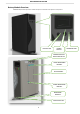
1.3.3 Stack Mount .................................................................................................................................................................... 23
1.4 Battery Terminal Function Definition .......................................................................................................... 25
1.5 Out of the Box Pre-Operational Check ........................................................................................................ 26
SECTION 2 - LOW VOLTAGE CONFIGURATION .................................................................................... 27
2.1 Product Introduction ................................................................................................................................. 27
2.1.1 Identifying the Individual Module.................................................................................................................................... 27
2.1.2 Accessory List (Standard Kit 120A Single Module LV)........................................................................................................ 29
2.1.3 Necessary Installation Tools ............................................................................................................................................. 30
2.1.4 Personal Protective Equipment +1000 Vdc Insulated Tools .............................................................................................. 30
2.2 Low Voltage Module Wiring and Set Up ...................................................................................................... 31
2.2.1 Battery Connection Terminals ......................................................................................................................................... 31
2.2.2 BATTERY CAN Pin Out ..................................................................................................................................................... 31
2.3 Low Voltage DIP Switch Settings ................................................................................................................ 32
2.3.1 LOW VOLTAGE PARALLEL CONFIGURATION ..................................................................................................................... 33
2.3.2 LED Visual Indication Lights ............................................................................................................................................. 33
2.4 Module Activation and Shutdown .............................................................................................................. 33
2.5 Low Voltage Parallel Set Up Overview ........................................................................................................ 35
2.5.1 Auto ID Assignment and DIP Configuration for LOW Voltage Single Cluster (Parallel Connection) ................................... 36
2.5.2 Single Cluster DIP and DATA Connection ......................................................................................................................... 38
2.5.3 Parallel Battery Wiring Connections ................................................................................................................................ 39
2.5.4 Low Voltage Single Stack Power and Data Connections (15-Modules Maximum) ............................................................. 40
2.5.5 LED Bar Indications .......................................................................................................................................................... 42
2.6 Stand Alone Battery Front Panel Control .................................................................................................... 43
2.6.1 Start Battery.................................................................................................................................................................... 43
2.6.2 Shut Down Battery .......................................................................................................................................................... 43
2.6.3 Low Battery – Force Charge ............................................................................................................................................. 43
2.7 Parallel Battery Configuration .................................................................................................................... 43
2.7.1 Activation of Parallel Batteries (From Master to last module for a maximum of 15) ........................................................ 43
2.7.2 Shutdown of Parallel Batteries ........................................................................................................................................ 44
2.7.3 LV Direct Parallel Connection WITHOUT Certified Inverter BMS Communication (Open-Loop) ........................................ 45
2.7.4 LV Direct Parallel Connection WITH Certified Inverter BMS Communication (Closed-Loop) ............................................. 46
2.8 Power Connection of a Single Cluster ......................................................................................................... 47
2.9 CAN HUB for Multi Cluster Configuration ................................................................................................... 49
2.9.1 Low Voltage CAN HUB Dimensions .................................................................................................................................. 51
2.9.2 Control Logic and Protection Limit ................................................................................................................................... 51
2.9.3 CAN Hub General System Description .............................................................................................................................. 52
2.9.4 Multi Cluster Configurations ............................................................................................................................................ 53
2.9.5 Master ID Set Up and Connection Diagram ...................................................................................................................... 54
2.9.6 Power Connection Example ............................................................................................................................................. 55
2.9.7 Conceptual Diagram of a Cluster composed by 5 clusters and 8 batteries each. ............................................................... 56