
I&O Manual

DEKA DURATION DD5300
5
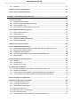
2.9.8 Conceptual Diagram between Master Modules of multiple clusters..................................................................................... 57
2.10 Cluster Configuration Accessories ............................................................................................................ 58
2.10.1 Single Cluster Configuration Kit ....................................................................................................................................... 58
2.10.2 Multi Cluster Hub Device ................................................................................................................................................. 58
2.11 Low Voltage Inverter Compatibility List ................................................................................................... 59
SECTION 3 - HIGH VOLTAGE CONFIGURATION ................................................................................... 61
3.1 Product Introduction ................................................................................................................................. 62
3.1.1 Identifying the Individual Battery Module ....................................................................................................................... 62
3.1.2 Product Identification and labels ..................................................................................................................................... 63
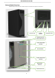
3.1.3 HV BOX Dimensions ........................................................................................................................................................ 64
3.1.4 Battery Module Accessory List (Standard Kit) .................................................................................................................. 65
3.1.5 HV BOX KIT (Included in the carton box) .......................................................................................................................... 66
3.1.6 Necessary Installation Tools ............................................................................................................................................. 67
3.1.7 Personal Protective Equipment + 1000 Vdc Insulated Tool Kit ......................................................................................... 67
3.2 High Voltage Battery Module Wiring and Set Up.......................................................................................... 68
3.2.1 Battery Connections ........................................................................................................................................................ 68
3.3 HV BOX Overview ..................................................................................................................................... 70
3.4 High Voltage Module Configuration ............................................................................................................ 72
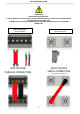
3.5 High Voltage DIP Switch Settings ................................................................................................................ 73
3.5.1 Serial Tower Connection #1 Set-Up of the HV Box CAN Communication Loop ................................................................... 74
3.6 Serial Battery Wiring Connections .............................................................................................................. 75
3.6.1 High Voltage Power Connections ..................................................................................................................................... 76
3.6.2 DATA Connections (Example of 12-Modules) ................................................................................................................... 77
3.6.3 HV Box and Battery Module Power Connection .............................................................................................................. 79
3.6.4 Single HV Box Connection to an Inverter ........................................................................................................................ 80
3.6.5 Multi HV Box Connection ................................................................................................................................................ 81
3.6.6 Multi HV Box Connection ................................................................................................................................................ 82
3.7 HV Box ADDRESS ....................................................................................................................................... 83
3.7.1 LED Visual Indication Lights ............................................................................................................................................ 85
3.7.2 Stand-Alone Battery Front Panel Control * FORCED CHARGE* ......................................................................................... 85
3.8 HIGH VOLTAGE INVERTER COMPATIBILITY ................................................................................................. 87
3.9 WECO BMS - LOW VOLTAGE PC SOFTWARE for DD5300 ............................................................................. 88
3.10 WECO BMS - HIGH VOLTAGE PC SOFTWARE for DD5300 ........................................................................... 92