ATS Stand OWNER’S MANUAL & SETUP INSTRUCTIONS CAUTION: Read all safety and operating instructions before using this equipment
ATS STAND (Document Part Number 158474) The MK Diamond ATS Stand is designed for use with the following MK Diamond products – MK-100, (Part No. 158189), MK-101 (Part No. 151991), MK-101Pro (Part No. 155747), MK-101 Pro24 (Part No. 153243), MK-115 Pro24 (Part No. 150341), MK-880 (Part No. 153261), MK-1080 (Part No. 153203), MK-2001 (Part No. 150597), and MK-2002 (Part No.
ATS STAND (Document Part Number 158474) Stand Assembly: Axle (A) Place the ATS Stand on its side and locate the axle Shaft Sleeve Valve Stem Axle Tire (B) Slide one Shaft Sleeve over the axle Axle (C) Insert the tire onto the axle with the valve stem facing out NOTE: Once the Tire Retaining Cap is installed, it is not easily removed. Ensure the Shaft Sleeve is installed and the tire is correctly oriented before performing Step D.
ATS STAND Rotate Knob clockwise to tighten (Document Part Number 158474) Front Leg Rotation Direction Retaining Knob (D) Rotate Front Leg up and tighten the Retaining Knobs Rotate Knob clockwise to tighten Verify the Retaining Knob is loose Rotate counterclockwise to loosen Rotation Direction (E) Loosen the two Rear Leg Retaining Knobs Rear Leg Front Leg ATS Stand (ATS Stand Part No.
ATS STAND (Document Part Number 158474) MK-100, 101, and 101 Pro Normal Cutting Head Position Installation: To ensure stability, verify front and rear legs of the ATS Stand are fully extended outward before installing the saw.
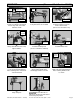
ATS STAND (Document Part Number 158474) Install into front hole on right side of stand Bracket C Bracket locations Nylock nuts Fit bracket over saw frame (J) Install one C Bracket and a Bolt into the top, front, of the ATS Stand as shown Rotate clockwise to install (K) Verify all brackets are installed (L) Install one Nylock nut on the Bolt of each bracket (Do not cross-thread the nut) Rotate clockwise to tighten Install Cutting Head (M) Using a 9/16-wrench and socket, tighten all Bolts (N) In
ATS STAND (Document Part Number 158474) MK-100, 101, and 101 Pro Extended Cutting Head Position Installation: To ensure stability, verify front and rear legs of the ATS Stand are fully extended outward before installing the saw.
ATS STAND Bracket C (Document Part Number 158474) Install into front hole on right side of stand Bracket locations Nylock nuts Fit bracket over saw frame (J) Install one C Bracket and a Bolt into the top, front, of the ATS Stand as shown Rotate clockwise to install (K) Verify all brackets are installed (L) Install one Nylock nut on the Bolt of each bracket (Do not cross-thread the nut) Rotate clockwise to tighten Install Cutting Head (M) Using a 9/16-wrench and socket, tighten all Bolts (N) Ins
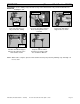
ATS STAND (Document Part Number 158474) Transport the MK-100, 101, and 101 Pro using the ATS Stand: Transport Position Front of Saw Frame ATS Stand Handle (A) ATS Stand in Transport Position (B) Transport the ATS Stand by the front of the saw frame or by the ATS Stand handle Setup/Takedown of the MK-100, 101, 101 Pro and ATS Stand: Ensure all bolts are tight before repositioning the ATS Stand.
ATS STAND (Document Part Number 158474) To ensure stability, verify front and rear legs of the ATS Stand are fully extended outward before installing the saw.
ATS STAND (Document Part Number 158474) MK-101 Pro and MK-115 Pro: To ensure stability, verify front and rear legs of the ATS Stand are fully extended outward before installing the saw.
ATS STAND Bracket C (Document Part Number 158474) Install into front hole on right side of stand Bracket locations Nylock nuts Fit bracket over saw frame (J) Install one C Bracket and a Bolt into the top, front, of the ATS Stand as shown Rotate clockwise to install (K) Verify all brackets are installed (L) Install one Nylock nut on the Bolt of each bracket (Do not cross-thread the nut) Rotate clockwise to tighten Install Cutting Head (M) Using a 9/16-wrench and socket, tighten all Bolts (N) Ins
ATS STAND (Document Part Number 158474) Transport the MK-101 Pro and MK-115 Pro using the ATS Stand: Transport Position Front of Saw Frame ATS Stand Handle (A) ATS Stand in Transport Position (B) Transport the ATS Stand by the front of the saw frame or by the ATS Stand handle Setup/Takedown of the MK-101 Pro, MK-115 Pro and ATS Stand: Ensure all bolts are tight before repositioning the ATS Stand.
ATS STAND (Document Part Number 158474) To ensure stability, verify front and rear legs of the ATS Stand are fully extended outward before installing the saw.
ATS STAND (Document Part Number 158474) MK-1080 and MK-880: To ensure stability, verify front and rear legs of the ATS Stand are fully extended outward before installing the saw.
ATS STAND Bracket C (Document Part Number 158474) Fit bracket over saw frame Install into top rear hole on right side of stand (J) Install one C Bracket and a Bolt into the top, front, of the ATS Stand as shown Nylock nuts Bracket C Fit bracket over saw frame Bracket locations Install into top hole on right side of stand (K) Install one C Bracket and a Bolt into the top, rear, of the ATS Stand as shown (L) Verify all brackets are installed Rotate clockwise to install Rotate clockwise to tighten
ATS STAND (Document Part Number 158474) Transport the MK-1080 and MK-880 using the ATS Stand: Transport Position Front of Saw Frame ATS Stand Handle (A) ATS Stand in Transport Position (B) Transport the ATS Stand by the front of the saw frame or by the ATS Stand handle Setup/Takedown of the MK-1080, MK-880 and ATS Stand: Ensure all bolts are tight before repositioning the ATS Stand.
ATS STAND (Document Part Number 158474) To ensure stability, verify front and rear legs of the ATS Stand are fully extended outward before installing the saw.
ATS STAND (Document Part Number 158474) MK-2000 Series: To ensure stability, verify front and rear legs of the ATS Stand are fully extended outward before installing the saw.
ATS STAND Bracket D (Document Part Number 158474) Fit bracket over saw frame Install into rear hole on left side of stand (J) Install one D Bracket and a Bolt into the rear, side, of the ATS Stand as shown Bracket D Fit bracket over saw frame Install into front hole on left side of stand Bracket D (K) Install one D Bracket and a Bolt into the front, side, of the ATS Stand as shown (L) Verify the two left-side D Brackets are installed correctly Nylock nuts Rotate clockwise to tighten Rotate clock
ATS STAND (Document Part Number 158474) Transport the MK-2000 using the ATS Stand: Front of Saw Frame Transport Position ATS Stand Handle (A) ATS Stand in Transport Position (B) Transport the ATS Stand by the front of the saw frame or by the ATS Stand handle Setup/Takedown of the MK-2000 and ATS Stand: Ensure all bolts are tight before repositioning the ATS Stand.
ATS STAND (Document Part Number 158474) To ensure stability, verify front and rear legs of the ATS Stand are fully extended outward before installing the saw.