www.mkdiamond.com MK-101-24 OWNER’S MANUAL & OPERATING INSTRUCTIONS MK-101-24 Part # 169612 Revision 104 11.2014 Manual Part No. 169689 Caution: Read all safety and operating instructions before using this equipment. This owners manual MUST accompany the equipment at all times.
INTRODUCTION Congratulations on your purchase of a MK-101-24 Tile Saw. We are certain that you will be pleased with your purchase. MK Diamond takes pride in producing the finest construction power tools and diamond blades in the industry. Operated correctly, your MK-101-24 should provide you with years of service. In order to help you, we have included this manual. This owners manual contains information necessary to operate and maintain your Tile Saw safely and correctly.
TABLE OF CONTENTS SAFETY Safety Messages General Safety Precautions & Hazard Symbols California Proposition 65 Message Electrical Requirements Electric Motor Safety Safety Label Locations Product Specifications 4 4-7 8 9 10-12 14 15 UNPACKING, TRANSPORT and ASSEMBLY Unpacking Contents Transport Stand (Optional) Assembly 16 16 17 17 18-20 SETUP, STARTUP, ADJUSTMENT, OPERATION and SHUTDOWN Setup Operation Cutting Head Adjustment Cleanup 21-23 24-27 28-29 30 MAINTENANCE AND TROUBLESHOOTING Maintenance T
MK-101-24 SAFETY Read and follow all safety, operating and maintenance instructions. Failure to read and follow these instructions could result in injury or death to you or others. Failure to read and follow these instructions could also result in damage and/or reduced equipment life. Safety warnings and guidelines do not by themselves eliminate danger. They are not substitutes for proper accident prevention procedures and good judgement.
MK-101-24 SAFETY PERSONAL PROTECTIVE EQUIPMENT always wear approved respiratory, head, ear and eye protection when operating this machine. ON )) (( (( (( ON (( ON ACCIDENTAL STARTS! )) )) Before starting the engine/motor, be sure the ON/OFF switch is in the OFF position to prevent accidental starting. Place the ON/OFF switch in the OFF position before performing any service operation. ALWAYS place the power ON/OFF switch in the OFF position when the saw is not in use.
)) MK-101-24 ON (( SAFETY (( ON USE PROPER APPAREL DO NOT wear loose clothing, gloves, neckties, rings, bracelets, or other jewelry that may be ))caught in moving parts. Non-slip footwear is recommended. Wear protective hair covering to contain long hair. SECURE WORK Clamps or a vise should be used to hold work whenever practical. Keeping your hands free )) to operate a power tool is safer. (( ON DO)) NOT OVERREACH Keep proper footing and balance at all times by not overreaching.
)) MK-101-24 ON (( SAFETY (( ON CHECK FOR DAMAGED PARTS Before using a power tool, check for damaged parts. A guard or any other part that is damaged should be carefully checked to determine if it would operate properly and perform its intended function. Always check moving parts for proper alignment or binding. Check for broken parts and mountings and all other conditions that may affect the )) operation of the power tool. A guard, or any damaged part, should be properly repaired or replaced.
MK-101-24 SAFETY SILICA DUST WARNING Grinding/cutting/drilling of masonry, concrete, metal and other materials with silica in their composition may give off dust or mists containing crystalline silica. Silica is a basic component of sand, quartz, brick clay, granite and numerous other minerals and rocks. Repeated and/or substantial inhalation of airborne crystalline silica can cause serious or fatal respiratory diseases, including silicosis.
MK-101-24 SAFETY ELECTRICAL REQUIREMENTS AND GROUNDING INSTRUCTIONS )) ON (( In order to prevent electrical shock and injury, the following electrical safety precautions and symbols should be followed at all times! WARNING In case of a malfunction or breakdown, grounding provides a path of least resistance for electrical current to reduce the risk of electric shock. This tool is equipped with an electric cord which has an equipment-grounding conductor and a grounding plug.
MK-101-24 SAFETY ELECTRIC MOTOR SAFETY (( For maintenance care and operation of the electric motor, refer to your electric motor instruction booklet furnished with the electric motor. Protect the electric motor from dust as much as possible and keep ON )) ventilating openings clean. Before plugging in the machine, make sure that the outlet voltage is within the voltage marked on the machines's data plate. CAUTION DO NOT spray water on the electric motor. Do not touch the plug with wet hands.
)) MK-101-24 ON (( SAFETY WARNING To avoid the possibility of the appliance or plug receptacle getting wet, position the machine to one side of a wall mounted receptacle. This will prevent water from dripping into the receptacle or plug. A "drip loop," shown in the picture below, should be arranged by the user to properly position the power cord relative to the power source. Use the drip loop as a way to prevent GFCI and plug from getting wet.
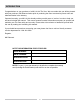
)) ON SAFETY (( MK-101-24 WARNING Use of undersized extension cords result in low voltage to the motor that can result in motor burnout and premature failure. MK Diamond warns that equipment returned to us showing signs of being run in a low voltage condition, through the use of undersized extension cords,will be repaired or replaced totally at the customer’s expense. There will be no warranty claim. To choose the proper extension cord, • Locate the length of extension cord needed in the table below.
NOTES 13
MK-101-24 SAFETY SAFETY LABEL LOCATIONS Safety labels contain important safety information. Please read the information contained on each safety label. These labels are considered a permanent part of your saw. If a label comes off or becomes hard to read, contact MK Diamond or your dealer for a replacement. G ! WARNING ! WARNING C For Your Own Safety Read Instruction Manual Before Operating Saw. Wear Eye Protection. Disconnect Saw Before Servicing, when Changing Cutting Wheels and Cleaning.
MK-101-24 PRODUCT SPECIFICATION PRODUCT SPECIFICATIONS The MK-101-24 is a versatile Tile Saw. Operated and used according to this manual, the unit will provide years of dependable service. The MK-101-24 is engineered as a table top or stand mounted wet tile saw. The saw include a powerful 120V totally enclosed capacitor start motor with a thermal protective overload. Specifications for the MK-101-24 Voltage 120V Overall Amperage 14.
MK-101-24 SAFETY UNPACKING Your MK-101-24 has been shipped from the factory thoroughly inspected. Only minimal assembly is required. CAUTION Use proper lifting techniques when lifting the MK-101-24. NOTE: A silicon plug on the cutting table covers the leveling set screw. This is a factory adjustment to ensure precision cutting.
MK-101-24 PRODUCT SPECIFICATION transport CAUTION 1. T he MK-101-24 weighs approximately ninety-eight (98) pounds. 2. N ever transport the MK-101-24 with water in the Water Basin. The MK-101-24 is designed with a rigid frame and removable Cutting Head. Two people are required to transport the MK-101-24 with the Cutting Head installed. Remove the Cutting Head if one person is transporting the saw (see Cutting Head Installation and Removal in the following section).
MK-101-24 ASSEMBLY cutting Head Installation Follow the assembly instructions to prepare your MK-101-24 for operation. NOTE: CAUTION If the cutting head is installed, go to the next step. The cutting head is heavy. Care must be used when installing it. (A) Ensure Cutting Head Stop is in upward position. (B) Align Cutting Head rear Pivot Hole to the Post Pivot Shaft and slide onto shaft. (C) Install the Cutting Head onto the Post Pivot Shaft and install the Adjusting Knob.
MK-101-24 ASSEMBLY Diamond Blade Installation NOTE: When installing the Retaining Nut, do not “cross-thread” and DO NOT over tighten. (A) Position Movable Cutting Table to the front of the saw. (B) Raise the Blade Guard by loosening the wingnut. (D) Depress and hold the Shaft Lock pushbutton and remove Retaining Nut and Outer Flange using the Blade Wrench. (E) Install Diamond Blade onto Blade Shaft.
MK-101-24 ASSEMBLY Adjustable Cutting Guide Installation NOTE: The Adjustable Cutting Guide can be used on either side of the Diamond Blade. (A) Place the Adjustable Cutting Guide onto the Movable Cutting Table Ruler/Stop and tighten the retaining thumbscrew. Splash Guard Installation (A) Install the retaining thumbscrew through the washer and Splash Guard then align to the hole found on back of the Blade Guard. (B) Install the Splash Guard onto the Blade Guard.
MK-101-24 SETUP Pre-start Inspection Prior to beginning work, a pre-start inspection of the saw should be performed. (A) Ensure the ON/OFF Switch is in the OFF position. (B) Verify the Movable Cutting Table moves freely. (D) Inspect the Pump Assembly for damage – ensure the cord is free of cracks or cuts. (E) Inspect the MK-101-24 for damage – ensure the cord is free of cracks or cuts. (C) Inspect the Diamond Blade for damage – verify the blade is correct for the material being cut.
MK-101-24 SETUP Water Pump Setup for Operation The Water Pump can be setup for operation in two ways, External Water Source or Re-circulation. NOTE: If using a dry blade for operation, DO NOT connect the water pump. External Water Source This is the preferred method of cooling. (A) Remove the Drain Plug. Place empty container under hole for water drainage.
MK-101-24 SETUP VOLTAGE: CYCLE: PHASE: 120V 60hz 1-phase 4. I f using an extension power cord, make sure, the length and wire gauge correspond to the requirements listed in on page 12. An extension power cord that is too small in wire gauge (diameter), or too long in length, will cause the motor to overheat and could cause premature failure. 5. Use an approved Ground Fault Circuit Interrupter (GFCI) 6. Do not cover the motor vents as this could lead to motor overheating.
MK-101-24 OPERATION Cutting Straight Edges CAUTION DO NOT FORCE THE TOOL. It will do the job better and safer at the rate for which it was designed. (A) Position the Adjustable Cutting Guide to desired cut length. (D) Verify proper cooling flow on both sides of the blade (See Maintenance Section to increase/decrease flow). (B) Tighten the retaining thumbscrew. (E) Perform the cut. Turn the motor OFF when work is complete. 24 (C) Place the tile against the Ruler/Stop and Cutting Guide.
MK-101-24 OPERATION Diagonal Cutting (Optional) NOTE: To cut diagonal, the Dual 45º Flat Angle Guide (MK Diamond Part No. 134577-MK) should be used. CAUTION DO NOT FORCE THE TOOL. It will do the job better and safer at the rate for which it was designed. (A) Remove the Adjustable Cutting Guide. (B) Position the Dual 45º Flat Angle Guide and tighten the retaining thumbscrew. (D) Verify proper cooling flow on both sides of the blade (See Maintenance Section to increase/decrease flow).
MK-101-24 OPERATION 45° Miter Cutting (Optional) NOTE: To cut 45º Miters, the 45º Bullnose Miter Guide (MK Diamond Part No. 153201-MK) should be used. CAUTION DO NOT FORCE THE TOOL. It will do the job better and safer at the rate for which it was designed. (A) Position the 45º Bullnose Miter Guide and tighten the retaining thumbscrew. (B) Position the tile on the 45º Bullnose Miter Guide and the Ruler/Stop. Turn the motor ON. (D) Perform the cut. Turn the motor OFF when work is complete.
MK-101-24 OPERATION Off-angle Cutting (Optional) NOTE: To cut angles other than 45º angles or Miters, a 90º Protractor (MK Diamond Part No. 134569-MK) should be used. CAUTION DO NOT FORCE THE TOOL. It will do the job better and safer at the rate for which it was designed. (A) Place the 90º Protractor on the Ruler/Stop. (D) Position the tile against the 90º Protractor and the Ruler/Stop. Turn the motor ON. (B) Set the desired angle and tighten the thumbscrew.
MK-101-24 ADJUSTMENT Adjusting the Cutting Head NOTE: For larger tiles and maximum cutting length, the cutting head should be in the front pivot hole. CAUTION The Cutting Head is heavy! Care must be used when changing the position of the Cutting Head. (A) Ensure the ON/OFF Switch is in the OFF position. Unplug the GFCI from the power source. (B) Remove the Blade. Remove Adjusting Knob. (D) Install the Cutting Head onto the front pivot hole. (E) Remove the Cutting Head Stop Bolt.
MK-101-24 ADJUSTMENT Adjusting the Post for Maximum Cutting Length CAUTION The Cutting Head and Post are heavy! Use care when changing the position of the Cutting Head. (A) Remove Water Basin and Blade. CAUTION (B) Remove the Cutting Head (See Adjusting the Cutting Head. (C) Loosen the Post Support and retaining bolts. Hold the Post when removing the Post Support Plate. (D) Remove the Post Support and Retaining Bolts. (E) Remove and relocate the Post to the rear Post retaining holes.
MK-101-24 CLEANUP CLEANUP NOTES 1. If an external water source was used, steps A through C may be skipped. 2. Dispose of waste water in accordance with applicable Federal, State and Local laws. (A) Place the Water Pump in an external container. CAUTION (C) Remove the Water Basin. Ensure the saw is disconnected before completing the remainder of the cleanup process. (D) Clean the Movable Cutting Table Guide Bar. CAUTION (B) Run the saw until clear water is seen at the blade cooling ports (Approx.
MK-101-24 MAINTENANCE MAINTENANCE Perform the following after initial purchase and operation of the MK-101-24. (A) Check and adjust V-belt tension following first 48 hours of operation (See V-belt Inspection). Maintenance Following Use To extend the life of the MK-101-24, the following procedure should be performed after each use. Lubricate all points listed below with light oils such as, 3 in 1, WD-40, etc. CAUTION Ensure the saw is off and disconnected before performing any maintenance.
MK-101-24 MAINTENANCE Monthly Maintenance The following maintenance should be performed Monthly. (A) Remove the Diamond Blade. (B) Lubricate the Outer Flange and Retaining-nut. (C) Lubricate the Arbor Shaft. (D) Verify the Roller Wheel Assembly is tight and in good condition. (E) Verify all motor mounting Bolts are tight. (F) Verify the Motor Adjustment Strap is tight. (G) Remove the Blade Guard. (H) Lubricate the Blade Guard Pivot Shaft.
MK-101-24 MAINTENANCE (J) Lubricate the Cutting Head Adjustment Knob. (K) Lubricate the Cutting Head Adjustment Knob retaining holes. (L) Lubricate the Cutting Head Pivot Shaft. Flow Adjustment NOTE: If flow to the diamond blade requires adjustment, perform the following actions. (A) Increase cooling flow by releasing the Flow Adjusting Clamp. (B) Reduce cooling flow by Pressing down on the Flow Adjusting Clamp.
MK-101-24 MAINTENANCE Diamond Blade Change-out NOTE: When installing the Retaining Nut, do not "cross-thread" and DO NOT over tighten the nut. (A) Locate the Shaft Lock push button on the underside of the Cutting Head (D) Install the new Diamond Blade onto Blade Shaft.
MK-101-24 MAINTENANCE Micro-V Belt Inspection, Adjustment and Replacement The MK-101-24 is designed with power transmission Micro-V Belt. In order to ensure the MK-101-24 operates a peak efficiency, the Micro-V Belt should be inspected monthly, and changed if the Micro-V Belt shows damage and/or excessive wear. NOTE: When a new belt is installed, it should be inspected and re-tensioned after the first fortyeight (48) hours of operation.
MK-101-24 MAINTENANCE (J) Push the motor toward the front of the Cutting Head to loosen the Micro-V Belt (K) Remove the Micro-V Belt (L) Install the new Micro-V Belt (MK Diamond Part No.
MK-101-24 TROUBLESHOOTING Blade will not cut properly (A) Check for Smoothness or “Glazing” (Dress blade if needed). (B) Check for proper blade rotation. (D) Verify the blade is correct for the material being used. Movable Cutting Table Does Not Move Correctly (A) Check the Guide Bar and Frame for cleanliness – clean if dirty. (B) Check the Movable Cutting Table Roller Wheels for wear – replace if necessary. 37 (C) Ensure the Blade Core is not bent.
MK-101-24 TROUBLESHOOTING Cooling Flow (A) Verify the cooling flow Adjusting Clamp is open. If flow exists, go to Step B. (B) Remove the Cooling Transfer Tube from the Blade Guard inlet. Go to Step C. (C) Place Pump into a bucket of water and check flow. If flow exists, go to Step D. (D) Remove the Cooling Transfer Tube and check for flow. If flow exists, refer to water pump manual. (E) Remove the Blade Guard Intake Fitting. Go to Step F. (F) Remove the Cooling Channel cover screws. Go to step G.
MK-101-24 TROUBLESHOOTING Blade Stops Turning (A) Allow motor to cool and depress motor Overload Reset Switch NOTE: (B) Verify all plugs fully installed. Check Ground Fault Circuit Interrupter Verify circuit breaker at least 20 amps - if not, move to 20-amp circuit. Verify circuit breaker not tripped. If tripped, reset once. Check power source voltage is 120V - if not 120V, move to another circuit.
MK-101-24 TROUBLESHOOTING Preparation for Alignment (A) Remove Water Pan. (B) Inspect Diamond Blade for damage. (C) Loosen front and rear Guide Bar Retaining Bolts. Horizontal Rough Alignment The Horizontal alignment will ensure that straight cuts (or Rip Cuts) are made. (A) Position Cutting Head to normal Cut Depth. (B) Move Guide Bar until Blade is centered in Cutting Groove. Tighten rear guide bar retaining bolt. (D) Position Square flat on Movable Cutting Table against Ruler/Stop.
MK-101-24 TROUBLESHOOTING Horizontal Alignment Verification (A) Move the Cutting Table back and forth to verify Blade is even across all points of Square. (B) Tighten Guide Bar Retaining Bolts. (C) Move the Cutting Table back and forth to re-verify Blade is even across all points of Square. 90° Alignment Verification 90º-alignment verification ensures the blade cuts tile straight up and down and not at an angle. The diamond blade must be removed and reinstalled when removing the blade guard.
4 23 13 14 3 26 1 21 2 16 15 7 6 10 5 22 11 8 9 20 12 24 19 17 18 MK-101-24 EXPLODED VIEW 42
MK-101-24 Item # PARTS LIST 1 Description HOSE, VINYL, 1/4 X 3/8 (6.0’) Part # Qty.
MK-101-24 EXPLODED VIEW & PARTS LIST 5 Table Assembly Part# 169598 2 3 4 1 8 9 2 3 6 4 7 Item # 1 CASTING, 101/990 LNR BRG MT-COM Description Part # Qty.
MK-101-24 EXPLODED VIEW & PARTS LIST Assy, Frame Part# 170477 3 8 5 6 1 2 4 7 9 Item # 1 WASHER, LOCK, SPLIT, 3/8 Description Part # Qty. 2 SCREW, SET, SOC, CUPT, 3/8-16X1/2 153710 1 3 SHAFT, 12.88 PIVOT 155530 1 4 PLATE, PRESSURE 155671 1 5 SCREW, 3/8-16 X 2-1/2 HEX HEAD CAP 156030 2 6 CASTING, POST, PRO24 OFFSET-COMP 158405 1 7 SPACER, 5/8 X .
MK-101-24 EXPLODED VIEW Cutting Head Assembly Part# 168167 13 7 INCLUDED WITH ITEM 8 1 10 5 11 2 3 8 12 2 6 5 3 9 46 4
MK-101-24 Item # PARTS LIST 1 Description KEY, 3/16 SQ X 1 - 18 Part # Qty.
MK-101-24 EXPLODED VIEW & PARTS LIST Blade Guard Part# 152582 2 1 4 3 Item # 1 Description SCREW, 5/16 - 18 X 1/2 SOCKET HD SET Part # Qty.
MK-101-24 EXPLODED VIEW & PARTS LIST 1 Table Assembly Part# 158191 9 10 13 3 8 11 10 1 23 12 20 2 22 4 19 21 18 17 7 Item # 14 5 16 15 1 NUT, HEX, 5/16 - 18 Description Part # Qty.
MK-101-24 THEORY THEORY OF DIAMOND BLADES Diamond blades do not really cut; they grind the material through friction. Diamond crystals, often visible at the leading edge and sides of the rim/segment, remove material by scratching out particles of hard, dense materials, or by knocking out larger particles of loosely bonded abrasive material. This process eventually cracks or fractures the diamond particle, breaking it down into smaller pieces.
NOTES 51
MK-101-24 ITEM 1. ACCESSORIES NUMBER 137166 DESCRIPTION MK-200. 10” X 5/8” ARBOR Premium grade Diamond Blade for smooth, chip-free cutting on tile. MK-215, 10” X 5/8” ARBOR Supreme grade diamond blade for hard materials 2. 128074 3. 153252 4. 134577-MK DUAL 45° FLAT ANGLE GUIDE 5. 153201-MK 45° Miter 6. 134569-MK 90° PROTRACTOR 7. 152792 DRESSING STONE 8. 152610 GROUND FAULT CIRCUIT INTERRUPTER 9.
NOTES 53
MK-101-24 ORDERING ORDERING INFORMATION You may order MK Diamond products through your local MK Diamond distributor or, you may order direct from MK Diamond. When ordering direct from MK Diamond, please have the following information ready before calling: • The Model Number of the saw • The Serial Number of the saw • Where the saw was purchased and when • The Part Number for the part(s) being ordered • The Part Description for the part(s) being ordered NOTE: There is a $25.
MK-101-24 Contact & warranty CONTACT: Please contact MK Diamond Products, Inc. Customer Service Department with any questions you might have regarding distributors, parts or service. Telephone: (800) 421-5830 Fax: (310) 539-5158 E-mail: Customer_Service@MKDiamond.com Customer Service Hours: Monday through Friday, 6AM-4PM PST MK Diamond Products, Inc. 1315 Storm Parkway Torrance, CA 90501 MK DIAMOND PRODUCTS, INC. LIMITED WARRANTY MK DIAMOND PRODUCTS, INC.
MK-101-24 TILE SAW OWNERS MANUAL & OPERATING INSTRUCTION MK Diamond Products, Inc. 1315 Storm Parkway Torrance, CA 90501 Toll-Free: (800) 421-5830 Phone: (310) 539-5221 Fax: (310) 539-5158 www.mkdiamond.