
Manual


MK-101 TRACKER Revision 06/05, Effective Date June 07, 2005
Page 22
SETUP, ADJUSTMENT and OPERATION
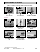
5. Adjusting the Cutting Head:
The Cutting Head is heavy! Care must be used when changing the position of the Cutting Head.
* A GFCI wall socket is the preferred protective device.
Adjust Cutting
Head to Cut Depth
of Approx ¼” to ½”
Turn Clockwise
to tighten
Turn Counter-
clockwise to loosen
Off
Position
ON/OFF
Switch
(C)
Remove Adjusting Knob
(A)
Ensure the ON/OFF Switch
is in the OFF position
(B)
Unplug the GFCI from the
power source*
(F)
Install the Adjusting Knob
(D)
Remove the Cutting Head from
The rear pivot hole
(E)
Install the Cutting Head onto
the front pivot hole
(G)
Set cutting depth approximately
1/4 to 1/2 inch below the surface
of the Movable Cutting Table
(H)
Plug the GFCI into the
power source*
Unplug
Remove
Cutting Head
Rear Pivot
Hole
Front Pivot
Hole
GFCI Plugged
Into Power
Source