bass management operation manual LFE-4 Miller & Kreisel Sound, Inc. 9351 Deering Avenue Chatsworth, CA 91311-5858 USA (818) 701-7010 fax (818) 701-0369 www.mkprofessional.com ©2003 Miller & Kreisel Sound, Inc.
Bass Management Controller TABLE OF CONTENTS 1. 2. 4. 5. 6. 7. 8. 9. 10. 11. 12. 13. 14. 15. SAFETY PRECAUTIONS..........................................................................................................3 M&K’S DESIGN PHILOSOPHY...................................................................................................4 THE LOGIC OF BASS MANAGEMENT, OBSERVATIONS BY KEN KREISEL..........................4 INTRODUCTION.....................................................................
Bass Management Controller The exclamation point within an equilateral triangle is intended to alert the user of the presence of important operating and maintenance (servicing) instructions in the literature accompanying the appliance. 1. CAUTION: TO PREVENT THE RISK OF ELECTRIC SHOCK, DO NOT REMOVE COVER (OR BACK). NO USERSERVICEABLE PARTS INSIDE. REFER SERVICING TO QUALIFIED SERVICE PERSONNEL.
Bass Management Controller 2. M&K’S DESIGN PHILOSOPHY Our philosophy is that exciting and lifelike sound and music reproduction takes place when your ears, in effect, become the recording microphones. Our speakers are designed to allow you to hear exactly what the microphones heard, placing you as close or as far away from the music or sound source as the recording engineer placed the microphones.
Bass Management Controller By combining a carefully designed low frequency acoustic rolloff of all the main speakers, including the surrounds, and a matching 2nd order electronic filter in the M&K Bass Management Controller, M&K achieves all the theoretical benefits of a 4th order Linkwitz-Riley filter.
Bass Management Controller The LFE-4 consists of a series of five high-pass filters (one each for the L, C, R, LS, LR channels) that route high frequency information (above 80Hz) to their appropriate channel’s amplifier and speaker monitor. Each channel is also routed through a matching 80Hz low-pass filter. This low frequency information is then routed to a summing amplifier, which in turn sends this low frequency information, along with the LFE channel, to two dual subwoofer outputs.
Bass Management Controller Input and Output Connector Wiring The XLR connectors on the LFE-4 are wired as follows: Pin 3: Pin 2: Pin 1: Minus Plus Ground General Connection Guidelines To avoid loud transients that may damage your speakers and hurt your ears, turn off your power amplifiers before connecting or disconnecting any cables or the power supply on the LFE-4. Certain types of audio cables have high capacitance in the range of 0.75pf/ft.
Bass Management Controller 6. CONNECTING FOR STEREO 1. Connect the left and right outputs of your mixer to the left and right input channels of the LFE-4. 2. Connect the left and right outputs of LFE-4 to the inputs of your power amplifiers or directly to your powered loudspeakers. 3. Connect one of the subwoofer outputs of the LFE-4 to the XLR input of your subwoofer.
Bass Management Controller 7. CONNECTING FOR DOLBY DIGITAL 1. Connect the left, center, right, left surround and right surround outputs of your mixer to the left, center, right, left surround and right surround input channels of the LFE-4. 2. Connect the outputs of LFE-4 to the inputs of your power amplifiers or directly to your powered loudspeakers. 3. Connect the mixer output assigned to the low frequency effects channel (LFE) to the +10dB input of the LFE-4. 4.
Bass Management Controller (Note: In order to gain an extra 10dB of headroom on the low frequency effects (LFE) channel, Dolby specifies that this channel be recorded 10dB lower than the 5 main channels. This 10dB lower level is made up in the playback chain to restore the correct 5 channel to .1 channel balance. For additional information please see the "Dolby Digital Professional Encoder Manual" which is available from the Dolby website. (www.dolby.com) 8. CONNECTING FOR DTS 1.
Bass Management Controller 5. If you are using passive speakers with external amplifiers, connect your speaker system to the power amplifiers. 6. Locate the external power supply for the LFE-4 and plug it into the 4 pin power connector on the back of the LFE-4. Secure it in place by turning the outer ring clockwise. Plug the external power supply into a power outlet. The front panel LED will glow red when power is applied. 9. CALIBRATING YOUR M&K PROFESSIONAL SYSTEM 1.
Bass Management Controller Track three: 10. 1 kHz sine wave recorded at –20dB FSD. Use this to set the reference level of your source (console, etc.) On an analog console this will be 0VU. On digital sources this will be either –20dB FSD or –18dB FSD. SPEAKER PLACEMENT There is considerable debate within the professional audio community as to the best speaker placement for multichannel mixing.
Bass Management Controller The speakers should be placed so that the tweeters are directly in line with the listener’s ears, that is, on-axis. (M&K powered speakers have a red LED recessed into the front baffle. The listener will know when his speakers are on-axis when he can see this LED. If this LED is not visible, either the speaker is turned-off or the speakers are aimed off-axis).
Bass Management Controller 13. SPEAKER CALIBRATION 1. Your speakers should now be in their final positions. 2. Remove all EQ and signal processing from the monitor path. 3. Turn all volume controls in the signal chain to their “reference level” position. These volume controls include the console main monitor pot, submaster faders and power amplifier volume pots. The “reference level” position is your defined reference playback level, which is typically 85dB SPL for film, video and music.
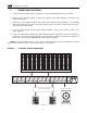
Bass Management Controller 15. LFE-4 SPECIFICATIONS All outputs have a +/- 12dB trim control for balancing the system . LCR and Surround channels: Input Impedance: Output Impedance: High pass filter: Nominal input level: Maximum recommended input level: Output clipping level: Gain Adjustment: THD ( 1kHz @+4 dBu): 20K ohm balanced 200 ohms balanced 80Hz- 12 dB/octave +4 dBu +24 dBu +27 dBu +/- 12dB 0.
7/08/2003 LFE-4 manual PN # 70360 rev.