Powered Subwoofer Operation Manual MPS-5410 MPS-5310 Miller & Kreisel Professional • 9351 Deering Avenue • Chatsworth • CA • 91311 • USA tel: (818) 701-7010 • fax: (818) 701-0776 • www.mkprofessional.com Miller & Kreisel Europe • Solrøed Center 12B, Level I • 2680 Solrøed Strand • Denmark tel: +45 56129047 • fax: +45 56129045 ©2004 M&K Sound, Inc.
The exclamation point within an equilateral triangle is intended to alert the user of the presence of important operating and maintenance (servicing) instructions in the literature accompanying the appliance. 1. CAUTION: TO PREVENT THE RISK OF ELECTRIC SHOCK, DO NOT REMOVE COVER (OR BACK). NO USERSERVICEABLE PARTS INSIDE. REFER SERVICING TO QUALIFIED SERVICE PERSONNEL.
TABLE OF CONTENTS 1. 2. 3. 4. 5. 6. 7. 8. 9. 10. 11. 12 13. 14. SAFETY INSTRUCTIONS....................................................................................2 INTRODUCTION..................................................................................................4 PACKING LIST.....................................................................................................4 M&K’S DESIGN PHILOSOPHY...........................................................................
2. INTRODUCTION Congratulations and thank you for purchasing this M&K powered subwoofer. Miller & Kreisel Professional powered subwoofers are designed to provide many years of accurate and problem free operation. We strongly encourage you to read this owner's manual, as there is a great deal of information provided here to help you get the best possible performance from your new M&K Professional subwoofer.
4. M&K’S DESIGN PHILOSOPHY Our philosophy is that exciting and lifelike sound and music reproduction takes place when your ears, in effect, become the recording microphones. Our speakers are designed to allow you to hear exactly what the microphones heard, placing you as close or as far away from the music or sound source as the recording engineer placed the microphones.
Bass Management psychoacoustically works because the ear-brain mechanism cannot detect direction at low frequencies, but takes its directional cues from the harmonics of the low frequency sound. In the monitoring process, frequencies below 80Hz are redirected to the subwoofer. Frequencies above 80Hz are sent to the desired speaker. During the hearing process, our hearing mechanism integrates the sound into the correct spatial auditory image.
Methodology For Placing Subwoofers The low frequency response and efficiency of a subwoofer are heavily influenced by the acoustics of the playback environment. More specifically, the response is influenced by the room’s dimensional ratios, types of construction and location of the subwoofer within that environment. You can significantly improve the subwoofer’s in-room response and efficiency by experimenting with various subwoofer placements until you find an optimum location.
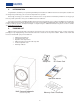
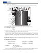
. INPUTS AND CONTROLS (MPS-5310 SHOWN AND SHOULD BE USED FOR REFERENCE ONLY, CONTROLS MAY NOT APPLY TO ALL MODELS) 1 2 3 A) Mono Balanced Input - 61K Ohms balanced input connector - 200mv in produces 90dB of output (Reference/THX input sensitivity mode). Pin Polarity: 1. Ground 2. Plus 3. Minus B) Variable Low-Pass Filter - 50Hz to 125Hz, 36dB per octave low-pass filter. This optional adjustment is activated by setting the 3-way toggle switch located to the right of this knob to the center position.
Anechoic Position- 3dB at 20Hz (anechoic) +/-1dB pass band (40Hz to 150Hz) -3dB at 200Hz In this position the subwoofer has the greatest low frequency extension and in small rooms often provides a rising characteristic below 35Hz. H) Input Gain Switch - In THX mode, the gain is fixed and provides 90dB of output when a 200mv signal is applied to the balanced input (100mv unbalanced). I) Variable Gain Knob - Variable gain knob provides gain settings from -∞ to approximately +20dB above reference.
c.) A small, flat bladed screwdriver (or “tweeker”) to adjust the channel trim pots on the LFE-4. d.) A CD player, or DVD player that can play CD-R’s. e.) An M&K speaker system with the LFE-4 Bass Management Controller. 2. It may be helpful to have one person sit at the listening position and read the meter while another person adjusts the trim pots on the LFE-4. 3.
8. tional. Do the same for all front (or main) speakers and point the meter at each speaker in turn. The meter’s microphone is direc- 9. Do the same for the surround speakers (Note: the film community prefers to use 82dB as the reference level for surround speakers while DVD authors, broadcasters and music mixers prefer to set all their speakers, including the surrounds, to the 85dB standard.
15. SPECIFICATIONS MPS 5410 (THX PM3 APPROVED) DRIVER COMPLEMENT CABINET TYPE 2 X 12” ACRYLIC POLYMER COATED CELLULOSE FIBER SEALED ENCLOSURE, INVERTED PUSH-PULL RATED POWER OUTPUT PEAK POWER OUTPUT (20 millisecond pulse) AMPLIFIER DISTORTION AMPLIFIER NOISE (relative to full output) 400 WATTS 550 WATTS < .
MPS 5310 (THX PM3 APPROVED) DRIVER COMPLEMENT CABINET TYPE 2 X 12” ACRYLIC POLYMER COATED CELLULOSE FIBER SEALED ENCLOSURE, INVERTED PUSH-PULL RATED POWER OUTPUT PEAK POWER OUTPUT (20 millisecond pulse) AMPLIFIER DISTORTION AMPLIFIER NOISE (relative to full output) 350 WATTS 480 WATTS < .
MPS 2810 DRIVER COMPLEMENT CABINET TYPE 2 X 8” ACRYLIC POLYMER COATED CELLULOSE FIBER SEALED ENCLOSURE, INVERTED PUSH-PULL RATED POWER OUTPUT PEAK POWER OUTPUT (20 millisecond pulse) AMPLIFIER DISTORTION AMPLIFIER NOISE (relative to full output) 200 WATTS 360 WATTS < .