LBI-38438A Maintenance Manual Service Section MLS High-Band Two-Way Mobile Radios MLSH041
GENERAL INFORMATION NOTICE! Repairs to this equipment should be made only by an authorized service technician or facility designated by the supplier. Any repairs, alterations or substitution of recommended parts made by the user to this equipment not approved by the manufacturer could void the user's authority to operate the equipment in addition to the manufacturer's warranty. NOTICE! The software contained in this device is copyrighted by Com-Net Ericsson Critical Radio Systems, Inc.
TABLE OF CONTENTS 1 DESCRIPTION ........................................................................................................................................4 2 INITIAL ADJUSTMENT........................................................................................................................4 2.1 TRANSMITTER ADJUSTMENT...............................................................................................4 2.2 RECEIVER ADJUSTMENT .................................................
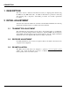
DESCRIPTION 1 DESCRIPTION The service section contains the information necessary for aligning and troubleshooting the MLS two-way FM mobile radio. In addition, information is provided for removing and replacing chip components, disassembly procedures and module replacement procedures. 2 INITIAL ADJUSTMENT After the radio has been installed as described in the Installation Manual, the following adjustments should be made by a certified electronics technician. 2.
MAINTENANCE 3 MAINTENANCE 3.1 PREVENTIVE MAINTENANCE To insure high operating efficiency and to prevent mechanical and electrical failures from interrupting system operations, routine checks should be made of all mechanical and electrical parts at regular intervals. Preventive maintenance should include checks detailed in the following sections. 3.1.1 Connections Ground connections to the voltage source should be periodically checked for tightness.
MAINTENANCE The PA transistor contains Beryllium Oxide, a TOXIC substance. If the ceramic or other encapsulation is opened, crushed, broken or abraded, the escaping dust may be hazardous if inhaled. Use care when replacing the module. WARNING 3.2 PA TRANSISTOR REPLACEMENT 1. Remove the two retaining screws securing PA transistors TR3 and TR4 to chassis assembly. 2. Unsolder and remove capacitors. Use a de-soldering tool as necessary while lifting the transistor leads with a small screwdriver or pick.
MAINTENANCE 3.3 CHIP COMPONENT REPLACEMENT Replacement of chip capacitors should always be done with a temperature controlled soldering iron, using a controlled temperature of 700ºF (371º C). However, do NOT touch black metal film of the resistors or the ceramic body of capacitors with the soldering iron. The metallized end terminations of the parts may be touched with the soldering iron without causing damage. NOTE 3.3.1 To Remove Chip Components 1.
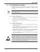
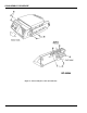
DISASSEMBLY PROCEDURE 4 DISASSEMBLY PROCEDURE 4.1 TO REMOVE THE SYSTEM CONTROL/SYNTHESIZER BOARD 1. Remove the two (2) screws (A) securing the top cover (refer to Figure 2). Remove the top cover. Then disconnect the interconnecting cables. 2. Remove the eight (8) screws (B) securing the Synthesizer shield. Remove the shield. 3. Remove the three (3) screws (D) securing the board. 4. Remove the screws (C) securing regulator and carefully lift up and remove the board. 4.
DISASSEMBLY PROCEDURES Figure 2 – Disassembly Procedure (Top View) Figure 3 – Disassembly Procedure (Bottom View) LBI-38438A 9
DISASSEMBLY PROCEDURE Figure 4 – Disassembly Procedure (Front Panel) 10 LBI-38438A
ALIGNMENT AND TROUBLESHOOTING PROCEDURES 5 ALIGNMENT AND TROUBLESHOOTING PROCEDURES Radio maintenance is facilitated by using the Troubleshooting Procedures and servicing techniques unique to this radio. The Troubleshooting Procedures are designed to lead the serviceman rapidly to the defective component or circuit. Troubleshooting procedures are provided for most major problems that might arise in the Transmitter, the Receiver, and the System Control/Synthesizer Board. 5.
ALIGNMENT AND TROUBLESHOOTING PROCEDURES 5.1.2 TX VCO & RX VCO Alignment CMC-232A 29.7 - 42 MHz STEP 1 METERING POINT TP201 Control Voltage Monitor TUNING CONTROL L206 METER READING PROCEDURE 4.0 VDC In case highest transmit frequency is < 34.0 MHz. Select lowest frequency transmit channel. With 50 ohm load on the antenna connector J1, key the radio. Monitor TP201 with digital voltmeter and tune L206 for 4.0 VDC ±0.1 V. Unkey the radio. 7.0 VDC 2 TP201 CV201 7.0 VDC 3 TP201 3.5-7.
ALIGNMENT AND TROUBLESHOOTING PROCEDURES METERING POINT TP201 Control Voltage Monitor TUNING CONTROL L206 METER READING 7.0 VDC 2 TP201 CV201 7.0 VDC 3 TP201 3.5-7.5 VDC 4 J201 +1 to +8 dBm STEP 1 5.1.3 PROCEDURE Select highest frequency transmit channel. With 50 ohm load on the antenna connector J1, key the radio. Monitor TP201 with digital voltmeter and tune L206 for 7.0 VDC ±0.1 V. Unkey the radio. Select the highest frequency receive channel.
ALIGNMENT AND TROUBLESHOOTING PROCEDURES 3. Connect the audio oscillator and apply a 1 kHz tone at 850 mVrms to MIC HI, J7014. Connect the deviation monitor to the antenna connector, J1 through a 30 dB decoupler. Key the radio. Set DEV ADJUST, RV201 for ±3.75 kHz deviation. 4. Set RV202 fully clockwise. Remove P602 from position 1-2 and set aside. Apply a 400 Hz tone to J602-2 and with the radio keyed, vary its amplitude until the Deviation Monitor reads 2 kHz. Note the level. 5.
ALIGNMENT AND TROUBLESHOOTING PROCEDURES 5.1.7 Audio Output Level Adjustment Procedure STEP METERING POINT TUNING CONTROL METER READING 1 J701-1 RV601 See Procedure PROCEDURE Set the signal generator to the receiver frequency with ±3 kHz deviation and 1 kHz modulation. Set the RF signal level to 1000 microvolts. Move P551 from J551-1, 2 to J5512, 3 on the Transmitter/Receiver Board. Connect RF signal generator to J1.
ALIGNMENT AND TROUBLESHOOTING PROCEDURES 5.2 TRANSMITTER Alignment and troubleshooting for Transmitter circuitry on the Transmitter/Receiver board CMN-233A/B. 5.2.1 General Description Of Adjustment This manual is prepared for adjustments and confirmations of the Exciter/PA section and covers the following items. 5.2.2 Measuring Instruments 1. AVR (DC Power Supply DC 0-20V, 20A) 2. Power Meter (usable at the value above 80 W) 3. Directional Coupler 4. Signal Generator 5. Spectrum Analyzer 6.
ALIGNMENT AND TROUBLESHOOTING PROCEDURES 5.2.3 Adjustment System 5.2.4 Transmitter Adjustment Procedure STEP 1 ITEM Initial Setting 2 Confirming the voltage TEST POINT TUNING CONTROL TP4 3 Setting APC off power RV1 RV2 4 5 LBI-38438A Confirming minimum power Confirming APC on power RV1 RV1 PROCEDURE Turn the volume on APC RV1, RV2 fully counterclockwise (CCW). Disconnect RF cable P101 from connector J201. Turn on the power. Turn on the PTT (ground J701-2).
ALIGNMENT AND TROUBLESHOOTING PROCEDURES 5.2.
ALIGNMENT AND TROUBLESHOOTING PROCEDURES LBI-38438A 19
ALIGNMENT AND TROUBLESHOOTING PROCEDURES 5.3 RECEIVER Alignment and Troubleshooting for Receiver Circuitry on Transmitter/Receiver Board CMN-233A/B. 5.3.1 Receiver Alignment 5.3.1.1 Equipment Required 1. RF Signal Generator (29 - 50 MHz) 2. DC Voltmeter 3. Frequency Counter (up to 100 MHz with 0.05 V sensitivity) 4. Audio Level Meter and Distortion Analyzer 5. 4 ohm, 6 Watt Resistor 5.3.1.2 Preliminary Adjustment 1. Connect 13.8 VDC to P2 2. Set MONITOR switch to “out” position 3.
ALIGNMENT AND TROUBLESHOOTING PROCEDURES 5.3.2 Alignment Procedure STEP 1 TEST POINT TP501 TUNING CONTROL 2 TP503 L513 METER READING PROCEDURE 9.0 ± 0.2 Connect the DC Voltmeter to TP501. VDC See Set the signal generator on the Procedure receive frequency with ±3 kHz deviation and 1 kHz modulation. Set the RF signal level to 1000 microvolts. Connect the audio level meter (use a high impedance meter) to TP503. 5 J701-1 -6 See Procedure Adjust the L513 until audio output level becomes maximum.
ALIGNMENT AND TROUBLESHOOTING PROCEDURES 5. Check that the squelch opens at an input signal level corresponding to 8 dB SINAD (±1 dB). 6. Remove ground from J701-7 or re-enable Channel Guard. 5.3.4 Receiver Test Procedures These Test Procedures are designed to help you service a receiver that is operating, but not properly. The problems encountered could be low power, poor sensitivity, distortion, and low gain.
ALIGNMENT AND TROUBLESHOOTING PROCEDURES 2. Place the RANGE switch on the Distortion Analyzer in the 200 to 2000 Hz distortion range position (1000 Hz filter in the circuit). Tune the filter for minimum reading or null on the lowest possible scale (100%, 30%, etc.). 3. Place the RANGE switch to SET LEVEL position (filter out of the circuit) and adjust the input LEVEL control for a +2 dB reading on a mid range (30%). 4. Set signal generator output to 0.3 V.
ALIGNMENT AND TROUBLESHOOTING PROCEDURES 5.3.5.
ALIGNMENT AND TROUBLESHOOTING PROCEDURES LBI-38438A 25
Com-Net Ericsson Critical Radio Systems, Inc. P.O. Box 2000 Lynchburg, Virginia 24501 Phone: 1-800-431-2345 or (Outside USA, 1-804-592-6100) www.com-netericsson.com A Printed in U.S.A.