LBI-38421A Maintenance Manual MLS II 150.8-174 MHz 40 WATTS MOBILE RADIO SUPPLEMENTAL DOCUMENTATION TRANSMITTER/RECEIVER ................................. LBI-38422 SYSTEM CONTROL/SYNTHESIZER .................. LBI-38423 FRONT PANEL/CONTROL UNIT ........................ LBI-38424 SERVICE SECTION ...............................................
LBI-38421A NOTICE! Repairs to this equipment should be made only by an authorized service technician or facility designated by the supplier. Any repairs, alterations or substitution of recommended parts made by the user to this equipment not approved by the manufacturer could void the user's authority to operate the equipment in addition to the manufacturer's warranty. NOTICE! The software contained in this device is copyrighted by Com-Net Ericsson Critical Radio Systems, Inc.
LBI-38421A TABLE OF CONTENTS SPECIFICATIONS* ...................................................................................................................................... 4 SAFETY SYMBOLS ...................................................................................................................................... 5 DESCRIPTION............................................................................................................................................... 6 OPERATION ..........
LBI-38421A SPECIFICATIONS* SYSTEM Radio Type FCC# MLSH041 Frequency Range: Transmitter Receiver Transmitter Receiver 150.8-174 MHz 150.8-174 MHz Two Frequency Spread 6 MHz Two Frequency Spread 3 MHz Battery Drain: Receiver (13.8 VDC) Off Squelched Unsquelched Transmitter (13.6 VDC) 0.03 Amperes 0.70 Amperes nominal 1.15 Amperes (4 Watts audio) 14.
LBI-38421A SPECIFICATIONS (continued)* RECEIVER Audio Ampl. Output (4-Ohm Speaker) 4 Watts (less than 5% distortion) EIA Sensitivity 12 dB SINAD (EIA method) 20 dB (Quieting method) 0.35 microvolts 0.40 microvolts Selectivity -70 dB ±30 kHz (EIA two-signal method) Spurious Response -70 dB Intermodulation -70 dB Modulation Acceptance ±7 kHz Frequency Response Within + 2.
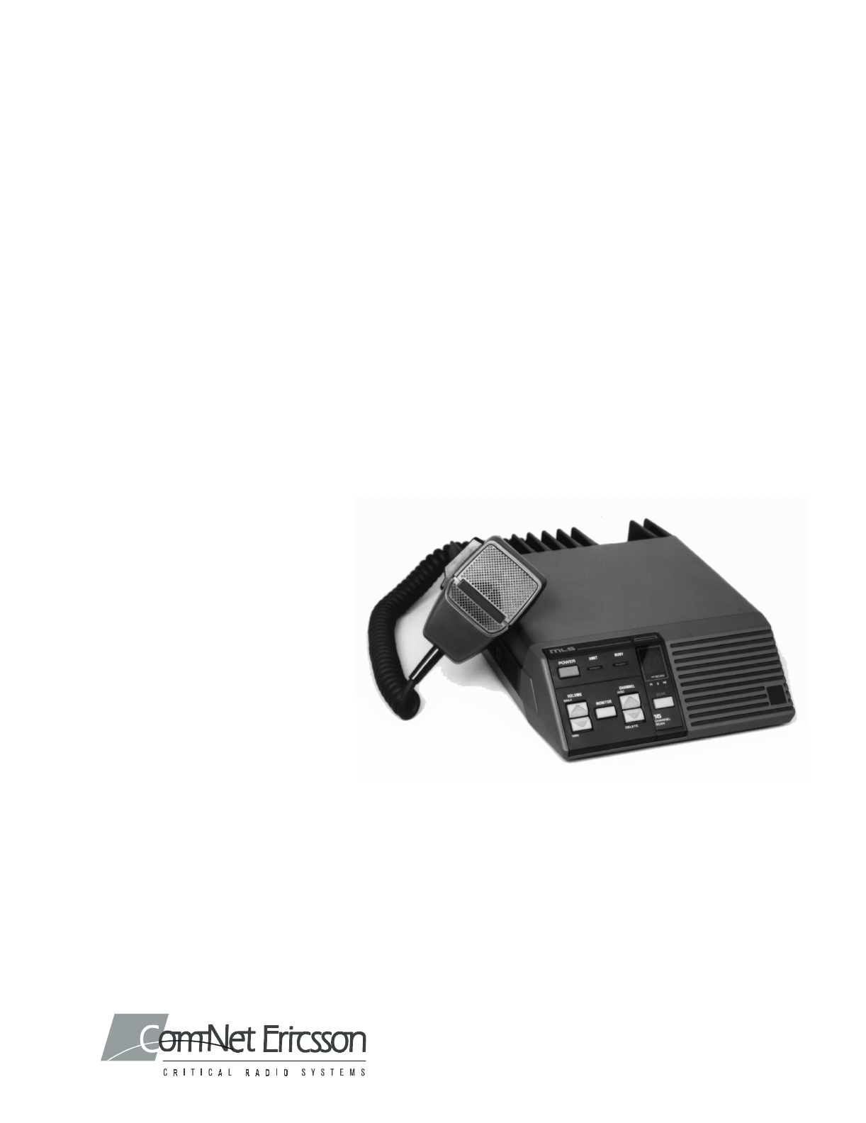
LBI-38421A DESCRIPTION The MLS II series mobile radio is a synthesized radio, utilizing microcomputer technology to provide high reliability, high quality and high performance in two-way, FM mobile communications. The MLSH041 radio operates in the 150.8-174 MHz frequency range and provides an RF power output of 40 watts with an allowable channel separation of 10 MHz transmit and 5 MHz receive.
LBI-38421A Figure 1- MLS VHF Mobile Two-Way FM Radio 7
LBI-38421A There are five (5) different optional interchangeable control panels available for selecting a two-channel radio, an eight (8) or sixteen (16) channel radio.
LBI-38421A CHANNEL Two momentary push type switches. Press CHAN 1 (up arrow) to select channel 1.; press CHAN 2 (down arrow) to select channel 2. The selected channel number will be illuminated on the control module. With an eight or sixteen channel radio two momentary type switches select the ADD switch to increase the Channel number; press and hold the DELETE switch to decrease the channel number. The selected channel is displayed by a 7segment display.
LBI-38421A Figure 3 - Eight Channel Radio Figure 4 - Sixteen Channel Radio With/Without Scan 10
LBI-38421A Using the Radio (Two (2) Channel) 2. Select the desired channel by pressing either the ADD or DELETE switch. 3. Press and hold MONITOR switch and then adjust the VOLUME controls for the desired listening level. Release MONITOR switch. 4. Radio is now ready to receive a message. To Receive a Message: 1. Confirm the radio is turned on (channel indicator lit). If not, press Power switch. 2. Select the desired channel by pressing either the 1 or 2 switch. 3.
LBI-38421A Scan operation will be determined by the following conditions: • Priority 1, and Priority 2 and Non-Priority Programmed* The Priority 1, Priority 2, and up to six (6) remaining channels in an eight (8) channel radio or fourteen (14) channels in a sixteen (16) channel radio will be scanned. Once a carrier is detected (or correct Channel Guard tone is decoded) the digital display will indicate the channel.
LBI-38421A included on the scan list. The scan indicator (S, P1, P2) will light for each channel programmed. Priority 2 (P2)**: 1. Perform steps 1 through 3 of the Non-Priority procedure. 2. Press and hold SCAN switch; then press the ADD switch twice. The selected channel will now become the Priority 2 channel and the “P2” indicator will light to indicate that the channel is now in the scan program as Priority 2.
LBI-38421A • Receiver Voltage Reading • IC and Chip Procedures Component a. On the Transmitter/Receiver Board (A802), connect jumper plug P502/551 across pins 1 and 2 of J502/J551 (IN). b. Verify that the internal speaker plug P503/P552 is connected to speaker jack J503/552. c. Locate the internal speaker in the front cap assembly and cut the two wires from the speaker terminals. d.
INTERCONNECTION DIAGRAM LBI-38421A Figure 1 - Interconnection DiagramFigure 2 15
LBI-38421A ILLUSTRATED MECHANICAL PARTS BREAKDOWN Figure 3 - Mechanical Parts Breakdown 16
PARTS LIST LBI-38421A 17
Com-Net Ericsson Critical Radio Systems, Inc. P.O Box 2000 Lynchburg, Virginia 24501 Phone: 1-800-431-2345 or (Outside USA, 1-804-592-6100) www.com-netericsson.com Printed in U.S.A.