
Data Sheet


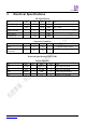


Table Of Contents

Everestek Inc.
www.everestek.biz Page 8
The 1Tx-3Rx system architecture is shown below,
Rx3
subwoofer
output
Rx1
Left
channel
output
I2S
Get_CCH
CCH_OK
P3.2
P1.6
P3.2
P1.6
I2C
VCC
P0.3
P0.3
VCC
ID
pairing
ID
pairing
P02
P02
P2.6
VCC
P2.6
wakeup
I2S
Get_CCH
CCH_OK
I2C
wakeup
P3.1
P3.1
P3.0
P3.0
Rx2
Right
channel
output
I2S
Get_CCH
CCH_OK
P3.2
P1.6
I2C
P0.3
VCC
ID
pairing
P02
P2.6
VCC
wakeupP3.1
P3.0
Tx
DSP
I2C
I2S
Get_CCH
CCH_OK
VCC
P3.2
P1.6
P2.6
VCC
P0.3
I2S
master/slave
ID
pairing
wakeup P3.1
P20
P0.3
Rx1: Left channel audio
Rx2: Right channel audio
Rx3: Subwoofer audio
RF operating frequency and RF modulation can be set by GPIO as the chart showed,
P0.7_CS
Float or pull up: narrow band
Tie to ground: wide band
P0.5_MISO
Float or pull up: 5.8G
Tie to ground: 5.2G
RF modulation & operation
frequency selection
`
Noe: deail operaion pleae refer o Everestek_EW21S_2.1_I2C Command Description.pdf docmen.
I2S signals connection is shown below, (pin number is 26-pin connector)