SERVICE MANUAL MOBILE GENERATORS SDG25S-6A7, SDG45S-6A6, SDG65S-6A6, SDG100S-6A6, SDG125S-6A6, SDG150S-6A6 MMD Equipment Inc. 121 High Hill Road Swedesboro, NJ 08085 Tel: (800) 433-1382 Fax: (856) 467-5235 www.mmdequipment.
Table of Contents 1. Specifications ......................................................................................................................................... 1.1 Specifications.................................................................................................................................... 1.2 Outline Drawing ................................................................................................................................ 1.3 Internal Components..............
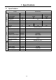
1. Specifications 1.1 Specifications Model SDG25S-6A7 Brushless Exciting system Armature connection Star with Neutral ZigZag Three Single 80 100 Generator Phase number Power factor % Frequency Hz 60 Rated output kVA 25 14.4 Rated output kW 20 14.
1.
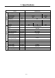
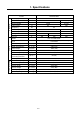
1. Specifications Model SDG65S-6A6 Brushless Exciting system Armature connection Star with Neutral ZigZag Three Single 80 100 Generator Phase number Power factor % Frequency Hz 60 Rated output kVA 63 36.5 Rated output kW 50 36.
1.
1.
1.
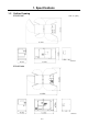
1. Specifications 1.2 Outline Drawing SDG25S-6A7 Unit : in.
1. Specifications SDG65S-6A6 Unit : in.
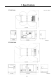
1. Specifications SDG125S-6A6 Unit : in.
1. Specifications 1.3 Internal Components SDG25S-6A7 1 2 3 4 5 6 13 12 11 10 9 8 7 A040574 1. Control panel 8. Battery 2. Engine 9. Engine oil level gauge 3. Air filter 10. Sedimenter 4. Engine oil filler port 11. Fuel filter 5. Reserve tank 12. Generator main unit 6. Radiator 13. Output terminals 7.
1. Specifications SDG45S-6A6 1 15 2 14 13 12 11 3 10 4 9 5 8 6 7 A040575 9. Filter for electromagnetic pump 1. Control panel 2. Engine 10. Fuel air-bleeding electromagnetic pump 3. Air filter 11. Battery 4. Reserve tank 12. Fuel filter 5. Engine oil filler port 13. Engine oil level gauge 6. Radiator 14. Output terminals 7. Fuel tank 15. Generator main unit 8.
1. Specifications SDG65S-6A6 1 2 15 14 3 13 4 12 11 5 6 7 8 10 9 A040576 9. Fuel tank 1. Control panel 2. Air filter 10. Engine oil filler port 3. Engine oil level gauge 11. Fuel air-bleeding electromagnetic pump 4. Reserve tank 12. Engine oil filter 5. Engine 13. Battery ※ 6. Sedimenter 14. Output terminals 7. Fuel filter 15. Generator main unit 8. Radiator Instrument 13 marked “※” are provided on the other side (opposite side of maintenance).
1. Specifications SDG100S-6A6 1 15 2 14 3 13 4 12 5 11 1. Control panel 6 10 7 9 8 A050016 9. Intercooler 2. Air filter 10. Fuel filter 3. Engine 11. Sedimenter 4. Engine oil level gauge ※ 12. Engine oil filter 5. Engine oil filler port ※ 13. Battery ※ 6. Reserve tank 14. Output terminals 7. Radiator ※ 15. Generator main unit 8. Fuel tank Instrument 4,5,7,13 marked “※” are provided on the other side (opposite side of maintenance).
1. Specifications SDG125S-6A6 1 2 17 16 3 15 4 14 5 6 13 12 11 7 10 9 8 A050157-1 1. Control panel 10. Intercooler 2. Air filter 11. Fuel filter 3. Engine 12. Engine oil filter 4. Reserve tank 13. Fuel pump 5. Engine oil level gauge 14. Fuel pre- filter 6. Engine oil filler port 15. Battery ※ 7. Exhaust muffler 16. Output terminals 8. Fuel tank 17. Generator main unit 9. Radiator Instrument 15 marked “※” are provided on the other side (opposite side of maintenance).
1. Specifications SDG150S-6A6 1 18 17 2 16 3 15 4 14 5 6 13 12 11 7 10 9 8 A050585 1. Control panel 10. Intercooler 2. Air filter 11. Fuel filter 3. Engine 12. Engine oil filter 4. Reserve tank 13. Fuel pump 5. Engine oil level gauge 14. Fuel pre- filter 6. Engine oil filler port 15. Battery ※ 7. Exhaust muffler 16. Output terminals 8. Fuel tank 17. Generator main unit 9. Radiator 18.
2. Overhauling 2.1 Cautions for Overhauling 2.1.1 Precautions before starting work (1) Work to be performed It is very important to always plan in advance what facilities, tools, instruments, materials, oil, etc. you will need to use; the exact locations and methods of performing inspection, adjustment, or disassembly; and the key points of any repair work to be performed. (2) Care not to spill oil Use a pan to collect used engine oil when changing the oil or attaching or detaching an oil line.
2. Overhauling 2.1.2 Disassembly and assembly (1) Wash dirt, dust and grime off vinyl tube and fuel hose before removing it, and take necessary steps to cover or tape the openings of vinyl tubes or fuel hoses to prevent any dirt from entering them. (2) Perform disassembly work in a dust-free location whenever possible. (3) When disassembling parts, wash their outer surface and place them on a clean sheet of paper or cloth, taking care not to contaminate or damage them.
2. Overhauling 2.2 Tightening Torque 2.2.1 General tightening torque of bolts and nuts Fasten all the bolts and nuts with the specified tightening torque when assembling. Type Strength, classification, and indication example Low or medium carbon steel bolt (SS400B, etc.) High strength steel bolt (SCM435, etc.) 8.8−12.9 (7T−12T) 4.6−6.8 (4T−6T) Indication does not appear in some cases.
2. Overhauling 2.2.2 Tightening torque for terminal plate When connecting the output terminals of the generator, it is important to tighten the screws, according to the designated torque. Since the terminal is so small, it could be burned or damaged without the proper torque. Bolt size M3.5 M4 M5 M6 M8 M10 M12 Tightening torque lbw・ft [N•m (kgf•cm)] 0.7 [1.0 (10)] 1.1 [1.5 (15)] 2.2 [ 3 (30)] 3.7 [ 5 (51)] 7.2 [10(100)] 12.
2. Overhauling 2.3 Disassembly/Reassembly of Generator Main Unit and Connection of Generator Main Unit and Engine 2.3.1 Disassembly of generator main unit The generator main unit is unilaterally mounted and the clearance is small, so it must be handled with extreme care to avoid the possibility of damage to the rotor or stator. Use hoisting equipment of sufficient capacity when it is necessary to lift up the engine and the generator main unit.
2. Overhauling (1) Procedures of disassembly 1. Remove cables from battery (-) terminal. 2. Remove brackets (or fittings for muffler, air filter and etc.) equipped on the bonnet. 3. Remove top cover and dismantle such parts on the bonnet so that generator main unit can be pulled out. 4. Remove cables and pipes. 5. Remove mounting bolts of generator main unit and engine. 6. Remove engine cooling fan guard and fan shroud. 7. If necessary, remove radiator, radiator hoses, fuel tank and battery. 8.
2. Overhauling 2.3.2 Measuring center deviation and surface deviation Measure them with a dial gauge pressed to the flywheel. (1) Measuring the center deviation, turn the rotor with the dial gauge pressed to the circumference of the coupling flange. If the biggest value measured on the same circumference exceeds 0.008in. (0.2mm), it is necessary to repair it. (2) Measuring the side run-out, turn the rotor with the dial gauge pressed vertically to the coupling flange.
2. Overhauling 2.3.3 Assembly of engine flywheel and generator coupling (rotor) The mounting holes are not equally spaced along the circumference. Therefore, position the holes in advance so as to match the coupling counterpart by turning and adjusting the engine flywheel. Use guide bolts while centering to mount the assembly. Tighten the bolts to the specified torque. (1) Mounting engine Mount the engine on the vibration isolator rubber at the frame side of engine.
2. Overhauling 2.3.4 Assembly of flywheel housing and generator main unit frame (stator) Handle the stator with care after fastening the engine flywheel and generator coupling, to avoid damage to either the rotor or stator. Tighten the connections to the specified torque. For connection of flywheel housing and generator main unit frame (stator), coat anti-corrosion agent “ METAL CLEAR” on the connecting faces to prevent rust and corrosion. Install the stator 1.
2. Overhauling 2.3.5 Mounting of generator main unit and engine on frame Perform centering carefully, to avoid deviation in the horizontal leveling caused by distortion of the frame or inaccurate mounting of the generator main unit and engine. Running the machine without accurate centering may cause abnormal vibrations.
2. Overhauling (1) Centering method 1. Mount the brackets on the engine secured to the generator main unit. (Use only genuine fastening bolts.) 2. Place four assembly level plates ※ on the points for mounting the engine and the generator main unit onto the frame. 3. Place the generator main unit with the engine mounted onto it on the assembly level plates on the frame. 4. Use shims for adjustment if joint gaps are found at any of the four places where the brackets and assembly level plates are to be fixed.
2. Overhauling (2) Check the gap between the cooling fan and fan shroud Maintain an adequate gap in both the vertical and horizontal directions. If the fan is mounted incorrectly so that it leans toward one side wall of the shroud, leading to a smaller gap in one direction, the fan may produce abnormal noise due to rubbing against the shroud during starting or stopping and may also overheat.
2. Overhauling 2.3.6 Changing the bearings in the generator main unit Use guide bolts to avoid the danger of dropping the bearing shield and to prevent the rotor and stator from rubbing against each other. (Use the guide bolts used to mount the generator main unit.) Do not hit the bearing outer race when installing or the bearing may be damaged. The generator main unit is quipped with fully sealed bearing. It is not necessary to supply grease.
2. Overhauling 2.3.7 Changing the rotary rectifier Care must be taken not to damage the rotary rectifier when mounting it on the conductive plate. When a soldering iron must be used on the rotary rectifier, make the contact time as short as possible. Degrease the portion where it should be coated with screw lock agent “Screw Loctite” for prevention of loose installation. The surge suppressor is integrated with the insulating plate and cannot be replaced separately.
2. Overhauling 2.4 Engine Maintenance Standards SDG25S-6A7 Engine model ISUZU AA-4LE1 DA-05 Tightening torque of head bolts Valve clearance Air intake Discharge Tighten M12 bolt according to the tightening torque of 61.5∼68.7lbw・ft [83.4∼93.2N・m(850∼950kgf・cm)] lbw・ft and further turn the bolt by 60∼90°angle. Then [N・m(kgf・cm)] tighten M8 bolt according to the torque of 18.1 ∼ 25.3lbw・ft [24.5∼34.3N・m(250∼350kgf・cm)]. in. (mm) in.
2. Overhauling SDG65S-6A6 Engine model Tightening torque of head bolts Valve clearance Air intake Discharge Firing order Injection timing (BTDC) Nozzle injection pressure Standard Compression Working limit Temperature for start of release Thermostat Full open temperature Valve lift ISUZU EE-4BG1TRD-02 First time 50.6 [69 (700)] lbw・ft Second time 65.1 [88 (900)] [N・m(kgf・cm)] Third time 90°∼120° (Angle tightening) in. (mm) 0.016 (0.4) [normal temperature] in. (mm) 0.016 (0.
2. Overhauling SDG125S/150S-6A6 Engine model Tightening torque of head bolts Valve clearance Air intake Discharge First time lbw・ft Second time [N・m(kgf・cm)] Third time in. (mm) in. (mm) Firing order Injection timing (BTDC) Nozzle injection pressure Standard Compression Working limit Thermostat Temperature for start of release Full open temperature Valve lift ° psi (MPa) psi (MPa) VOLVO TAD-720GE 37 [ 50 ( 510)] 96 [130 (1326)] 90° (Angle tightening) 0.014 (0.35) 0.022 (0.
3. Electrical Parts 3.1 Installation Positions of Electrical Appliances SDG25S-6A7 B A 1 2 3 12 4 5 11 10 9 8 7 6 13 VIEW-B VIEW-A 1. Thermal relay 8. Safety relay 2. Automatic voltage regulator (AVR) 9. Solenoid relay 3. Starter relay 10. Voltage selector switch 4. Charge relay 11. Three-phase circuit breaker 5. Glow relay 12. Current transformer 6. Terminal plate 13. Automatic operation unit 7.
3. Electrical Parts SDG45S-6A6 1 2 3 4 5 6 12 7 11 10 9 8 SG06009 1. Current transformer 7. Safety relay 2. Thermal relay 8. Solenoid relay 3. Automatic operation unit 9. Automatic voltage regulator (AVR) 4. Time relay 10. Terminal plate 5. Charge relay 11. Voltage selector switch 6. Heater relay 12.
3. Electrical Parts SDG65S-6A6 1 2 3 4 5 6 12 7 11 10 9 8 SG06010 1. Current transformer 7. Time relay 2. Thermal relay 8. Motor stopper relay 3. Automatic operation unit 9. Automatic voltage regulator (AVR) 4. Magnetic switch 10. Terminal plate 5. Glow relay 11. Voltage selector switch 6. Safety relay 12.
3. Electrical Parts SDG100S-6A6 1 2 3 4 5 6 7 12 11 10 9 8 SG06011 1. Current transformer 7. Motor stopper relay 2. Thermal relay 8. Glow relay 3. Automatic voltage regulator (AVR) 9. Magnetic switch 4. Automatic operation unit 10. Terminal plate 5. Safety relay 11. Voltage selector switch 6. Time relay 12.
3. Electrical Parts SDG125S/150S-6A6 1 2 3 4 5 11 10 9 8 7 6 SG06012 1. Automatic voltage regulator (AVR) 7. Terminal plate 2. Automatic operation unit 8. Voltage selector switch ※ 3. Magnetic switch 9. Three-phase circuit breaker 4. Glow relay 10. Current transformer 5. Starter relay 11. Thermal relay 6. Controller (Control unit EDC 4) ※The voltage selector switch of SDG150S-6A6 is provided on the output terminal plate of the right bonnet.
3. Electrical Parts 3.2 Electrical Parts of Generator 3.2.1 Rotary rectifier 1.Silicon rectifier 2.Varistor 3.Conductive plate 4.Insulating plate 5.Lead wire (alternator) 6.Lead wire (Exciter) AS-016 cathode C ● A ● anode How to check whether silicon rectifier (diode element) functions correctly or not Check the silicon rectifier (diode element) according to the resistance range of circuit meter.
3. Electrical Parts 3.2.2 AS (Ammeter change-over switch) SG06014 Diagram: AS for SDG25S-6A7,SDG100S/125S-6A6 SG06015 Interior cable connection 3.2.
3. Electrical Parts 3.2.4 AVR (Automatic voltage regulator) SDG25S-6A7,SDG45S−150S-6A6(AVR model : DST-100-2FA/2FA4) (5) (1) (4) (2) (3) 9 Pin(female) 6 Pin(female) 1:Brown 4:Yellow 7:Purple 1:Brown 4:Yellow 2:Red 5:Green 8:Gray 2:Red 5:Green 3:Orange 6: / 9: / 3:Orange 6: / SG06019 (1) (2) (3) (4) (5) Name V. F. ADJ VOLT. ADJ STAB.
3. Electrical Parts AVR is adjusted and set prior to delivery from factory. Accordingly, it is not necessary to adjust it unless the machine equipped with a new AVR functions abnormally. If upon test operation, there is any trouble such as voltage hunting, adjust it according to the following procedures. Adjustment of AVR 1.Start engine, and adjust the frequency to 62.5Hz at no load operation. 2.Turn the voltage adjuster (hand trimmer) on the instrument panel fully to the right to the maximum position. 3.
3. Electrical Parts Adjusting V/Hz characteristic If at the start stage of engine, voltage adjustment and stability adjustment have been already done, it is not necessary to adjust the V/Hz characteristic. But if at no load operation any trouble of voltage adjustment function occurs, or voltage disappears, adjust V/Hz characteristics, according the following procedures. 1. TurnV/Hz characteristics volume knob(V.F.ADJ) fully clockwise. (Notching position ;10/10) 2.
3. Electrical Parts 3.2.
3. Electrical Parts 3.3 Electric Parts of Engine 3.3.1 Alternator SDG25S-6A7 AS-006 AS-017 Voltage − Current 12V−20A Regulator adjusted voltage 13.8V±0.
3. Electrical Parts SDG45S-6A6 Interior cable connection SG06044E (1) List of functions Line Pin No.
3. Electrical Parts SDG65S-6A6 AS-011 Voltage − Current 24V−20A Regulator adjusted voltage 28.5V±0.5V SDG-005 SDG100S-6A6 SDG-004 Voltage − Current 24V−25A Regulator adjusted voltage 28.
3. Electrical Parts 3.3.2 Controller SG06045E SDG25S-6A7,45S∼100S-6A6(Emergency controller) List of functions Pin Line No. color 1 ※1 L/R (Y/R) 2 W/R 3 4 B - 5 L/Y 6 W Connection Function During normal operation the interior contact is ON between No.1 terminal and No.8 terminal. ※2 When emergency stop device functions, the interior Solenoid (motor stopper) relay contact will be OFF between No.1 terminal and No.1 terminal No.
3. Electrical Parts Pin No. Line color Connection Function During normal operation, engine water temperature switch is kept ON. The contact between No.1 and No.8 terminals becomes OFF at the condition OFF of engine water temperature switch, it cuts electric Engine water temperature 7 G/W supply to solenoid (motor stopper) relay so that switch for emergency stop engine can be stopped.
3. Electrical Parts SG06063 SDG125S/150S-6A6(Control unit EDC 4) List of functions Pin Line Connection No. color M-1 NIL M-2 NIL Glow relay No.2 terminal M-3 L/Y Emergency indicator CN16-5 terminal M-4 NIL Fuel temperature sensor No.1 M-5 terminal M-6 NIL M-7 NIL Fuel temperature sensor No.2 terminal M-8 Coolant temperature sensor No.2 terminal Coolant temperature sensor No.1 M-9 terminal Speed sensor (option) No.1 M-10 terminal Speed sensor (option) No.2 M-11 terminal M-12 Speed sensor No.
3. Electrical Parts Pin No. F-1 F-2 Line color B - Connection Grounding NIL F-3 G/W Emergency terminal indicator F-4 L/B Emergency terminal indicator F-5 F-6 F-7 F-8 F-9 F-10 F-11 F-12 F-13 B/L B/W - F-14 R/Y F-15 G/R F-16 - F-17 Y/B F-18 F-19 F-20 F-21 F-22 - Function When engine water temperature rises, the interior contact between F-3 and F-1 terminals becomes ON and electrically conducted. Then the warning lamp for engine water CN16-7 temperature rise goes on.
3. Electrical Parts Pin No. Line color F-23 B F-24 W F-25 R Connection Function Speed control knob (Engine speed potentiometer) (-) terminal Speed control knob (Engine speed potentiometer) signal input terminal Speed control knob (Engine speed potentiometer) (+) terminal Grounding Engine speed can be adjusted minutely by changing resistance between F-24 and F-23 terminals.
3. Electrical Parts 3.3.3 Emergency indicator SG06064 SDG125S/150S-6A6 List of functions Line Pin No. color CN15-1 L CN15-2 W/G Connection Function Auto start unit CN7-6 terminal Tachometer No.4 terminal List of functions Line Pin No. color Connection Function CN16-1 Y/L Auto start unit CN7-3 terminal CN16-2 W/Y Alternator W terminal CN16-3 B CN16-4 Y/B CN16-5 L/Y CN16-6 L/B Put in the engine revolution pulse converted for tachometer by PLC unit of auto start unit.
3. Electrical Parts Pin No. Line color CN16-7 G/W CN16-8 B/Y CN16-9 G/L CN16-10 R/Y CN16-11 L/W CN16-12 G/Y CN16-13 G/R Connection Function When engine water temperature rises, it is electrically conducted to make warning lamp glow. Controller F-3 terminal Auto start unit CN7-9 terminal Air filter differential pressure Grounding indicator Power supply (DC24V power) for engine Auto start unit CN7-1 terminal revolution pulse between CN16-1 and CN16-8 terminals.
3. Electrical Parts 3.3.4 Auto start unit (Automatic operation unit) CONNECTOR SG06026 SDG25S-6A7,45S∼100S-6A6 List of functions Pin Line No. color 1 Connection ※1 R/Y Manual-Auto selector switch (Y/R) 2 W ※2 Alternator R (L) terminal 3 W/R Controller No.2 terminal 4 L/W Controller No.11 terminal Function Power for auto start unit. With No.
3. Electrical Parts Pin No. Line color 5 Y/W 6 - Connection Remote start/stop switch connection terminal. When the remote start/stop switch is switched ON with No.1 terminal of auto start unit conducted electrically, XO relay begins to function. Consequently, the relay is put in order and power is supplied to PLC unit through ※3 [voltage regulator (VR1)] and DC-DC converter (DC1).
3. Electrical Parts CONNECTOR SG06027 SDG125S/150S-6A6List of functions Line Pin No. color Connection Power for XO relay of remote start /stop switch. With auto start unit No.1 terminal electrically conducted, when remote start/stop switch (exterior output terminal plate between A1-A2 terminals) is switched ON, XO relay begins to function. Power for hour meter functioning signal.
3. Electrical Parts Pin No. CN6-6 Line color B/R 15A fuse Connection Function Power supply for auto start unit. ●Manual starting operation Power supply for auto start unit. During manual operation, power is supplied to hour meter functioning signal output, engine revolution speed detection and change, prevention of starter motor overrunning, air filter clogging detection are performed by auto start unit. ●During automatic operation Power supply for engine starting.
3. Electrical Parts List of functions Line Pin No. color CN7-1 G/L CN7-2 Y/G CN7-3 Y/L CN7-4 W/L CN7-5 G/Y CN7-6 L CN7-7 L/W CN7-8 - CN7-9 B/Y T7 - T9 - Connection Function Power supply (DC24V) for output of engine revolution pulse outputted between emergency indicator CN16-1 and CN16-8 terminals. Air filter differential pressure Detection of air filter differential pressure indicator indicator clogging. Input of engine revolution pulse.
3. Electrical Parts 3.3.5 Glow timer SDG25S-6A7,SDG65S-6A6(QOSⅢ timer) 4 1 5 2 6 (1) List of functions Pin Line Connection No. color 1 B Grounding 3 Function For exciting glow relay For pre-heating function, it forms excitation circuit with connection of No.1 terminal (grounding). When starter switch is switched ON, pre-heat lamp 2 G/R Glow relay goes on and pre-heating starts. While starter motor starting signal is inputted to No.6 terminal from safety relay No.
3. Electrical Parts (2) Characteristics of water temperature and glowing time (Key OFF→ON) SDG25S-6A7 Water temperature Lamp glows・Glowing time t1 (seconds) [°F (℃)] 5 (-15) 5 68 (20) 2 122 (50) 1 SDG65S-6A6 Water temperature [°F (℃)] 5 (-15) 41 (5) 104 (40) (3) Chart of function ※(st) Starter Lamp glows・Glowing time t1 (seconds) 5 1 0.5 st ST ON Switch OFF t1 ON Lamp OFF t1 ON Glow OFF ※(st) shows the chart of function at which the starter switch is located at the st point.
3. Electrical Parts SDG45S-6A6 (QHS controller) SG06065 (1) List of functions Pin Line Connection No. color 1 NIL 2 R/W 10A fuse 3 W Alternator L terminal 4 G/R Heater relay excitation coil 5 L/Y Controller No.5 terminal 6 7 8 B B/W R/L Grounding Water temperature sensor Starter switch C terminal Function Power supply Detection of generation signal In case that no start signal is sent to No.3 terminal after No.8 terminal detects start signal, it cuts the output of No.
3. Electrical Parts (2) Water temperature and glow time characteristics (Key OFF→ON) Water temperature Lamp glows and glowing time t1 Time of afterheating t2 [°F (℃)] (seconds) (seconds) 5 (-15) 19 190 32 ( 0 ) 2 75 50 (10) 1 48 (3) Chart of function ※(st) ST st Starter ON Switch OFF t1 ON Lamp OFF t1 t2 ON Glow OFF The location marked ※ shows the chart of function located at the point where the starter switch is located at the position (st).
3. Electrical Parts SDG100S-6A6(QOSⅡ) SG06046E (1) List of functions Pin Line Connection No. color 1 R/W 10A fuse 2 B/W Water temperature switch 3 W/Y Safety relay C terminal 4 G/R Glow relay 5 B Grounding 6 L/Y Controller No.5 terminal Function Power supply Detection of water temperature Detection of start signal Power supply for excitation of glow relay When start signal is inputted to No.3 terminal, it preheats irrespective of water temperature.
3. Electrical Parts (2) Water temperature and glow time characteristics (Key OFF→ON) Lamp lighting time t1 Pre-glow time t2 Water temperature (seconds) (seconds) Within 8 30 50±37°F (10±3℃) More than 0.3 0 50±37°F (10±3℃) (3) Chart of function (st) ※1 ST After glow time t3 (seconds) 30 0 st Starter ON Switch OFF t1 ON Lamp OFF t2 ※2 t4 ※3 t3 ON Glow OFF ※1:(st) shows the chart of function at the location where the starter switch is positioned.
3. Electrical Parts 3.3.6 Safety relay SDG45S-6A6 SG06023E SG06024 List of functions Pin Line No. color Connection Function B Y Starter motor B terminal Battery (+) Power supply for starting of starter motor S W Starter motor S terminal When voltage is applied to No.1 terminal, the contact between B-S terminals turns ON, it applies voltage to starter terminal. 1 R/L Starter switch C terminal Auto start unit No.
3. Electrical Parts SDG65S/100S-6A6 The R in the parenthesis shows connection point of SDG100S. SG06025E Function 1) Starting operation while stopping • When voltage is applied to S terminal from starter switch or auto start unit No.8 terminal, the input from B terminal will be outputted from C terminal , and starter begins to rotate and then engine starts. • When the output voltage DC21.
3. Electrical Parts 3.3.7 Tachosensor SDG65S-6A6 (1) Checking whether voltage generated between terminals is proper or not With the clearance of 0.0295in. (0.75mm) between the feed During pump cam and the extreme end operation at of tachosensor, it is proper if the the rated voltage generated between conditions tachosensor terminals is more than 1.4V. To measure the voltage generated between tachosensor terminals, measure it using ACV range of digital tester.
3. Electrical Parts 3.3.8 Tachometer (with hour meter) SDG25S-6A7,SDG45S∼150S-6A6 SG06028 The figure shows the tachometer at of SDG25S/45S/125S/150S (1) Specifications Operation voltage Operation temperature Revolution ratio (pulse type) SDG25S/45S/125S/150S SDG65S/100S 10∼16V 20∼30V -4∼140°F (-20∼60℃) 2 revolutions per 1 pulse (2) List of functions Line Pin No.
3. Electrical Parts 3.3.9 Stop solenoid SDG25S-6A7 SDG-006 (37.2Ω) (0.537Ω) SG06029E SDG45S-6A6 SG06030E (1) Specifications Suction coil Holding coil 41A 0.75A SG06031E (2) Function Turning starter switch ON, voltage is applied to plus (+) terminal, and current flows to parallel circuit of suction coil and holding coil to pull the plunger for stop solenoid at once.
3. Electrical Parts 3.3.10 Motor stopper SDG65S/100S-6A6 SG06032E (1) List of functions Pin No. Line color Connection 2 L/B (L/W) Motor stopper relay No.5 terminal (NO) 3 G/L (L) Motor stopper relay No.3 terminal (COM) 4 B Grounding 5 Y/R (L/Y) Motor stopper relay No.6 terminal (NC) 6 W/G (L/R) 10A(20A) fuse The line colors in parenthesis show those of SDG100S. Function For power supply (2) Function of motor stopper 1.
3. Electrical Parts 2. Engine starts SG06034E 1) When closing ACC contact (“operation” position) for starting engine by handling starter switch, the following circuit will be formed ; controller interior contact → motor stopper relay No.1 terminal → excitation coil → motor stopper relay No.2 terminal → grounding and then the excitation coil of motor stopper relay will be excited. Consequently, the motor stopper relay contact begins to function.
3. Electrical Parts 3. Rotation of contact plate SG06035E 1) When motor begins to rotate, the worm fitted to the motor shaft rotates and at the same time worm wheel rotates. 2) The worm wheel and contact plate are interconnected and so it continues to rotate as shown in Fig c. 4. Stop of contact plate rotation SG06036E 1) When contact plate turns to 180˚ from the position at which it does not begin to rotate, there will be no conductivity between No.6 and No.2 terminals, and then No.
3. Electrical Parts 5. Engine stops (normal stop) SG06037E 1) To stop engine, handle starter switch to open BR contact (“Stop” position) so that excitation circuit of motor stopper relay may be released to move the contact point as shown in Fig e. 2) As battery voltage is applied to motor stopper relay No.6 terminal, the following circuit is formed: motor stopper relay No.3 terminal → motor stopper assembly No.3 terminal → motor → grounding, and motor rotates and contact plate rotates.
3. Electrical Parts 3.3.11 Fuel gauge SDG25S-6A7,SDG45S∼150S-6A6 SG06038E (1) Position of meter pointer Pointer position Resistance value (Ω) Remaining fuel [gal. (L)] E 95 ※ approx. 4.6 (17.5) 1/2 32.5 9.9 (37.5) F 7 ※ approx. 17.0 (64.5) ※ marked : The figures of the remaining fuel in the table are for model SDG25S-6A7. (2) List of functions Pin No.
3. Electrical Parts 3.3.12 Sending unit SDG25S-6A7 (equipped with thermistor sensor) SG06066 (1) Position of meter pointer for resistance value Pointer position Resistance value (Ω) Remaining fuel [gal. (L)] E 110 4.6 (17.5) 1/2 32.5 9.9 (37.5) F 3 17.0(64.5) (2) Specification of thermistor (for warning lamp indicating the shortage of remaining fuel) Rated voltage DC 12V Useful voltage DC 11∼15V Rated load DC12V 3.
3. Electrical Parts SDG45S∼150S-6A6 Meter indicates F (Full) from this position Meter indicates E (Empty) from this position Diagram: Sending unit for SDG100S to SDG150S SG06039 Pointer position Resistance value (Ω) E 1/2 F 110 32.5 3 SDG45S 5.0 (19) 15.6 (59) 24.6 (93) 3-45 Remaining fuel [gal. (L)] SDG65S SDG100S SDG125S 3.7 (14) 14.8 (56) 11.1 (42) 21.4 (81) 35.7 (135) 37.5 (142) 31.4 (119) 53.1 (201) 60.0 (227) SDG150S 3.7 (14) 41.0 (155) 66.
3. Electrical Parts 3.3.13 Electro-magnetic pump for bleeding air from fuel line 1. Type without filter SDG25S-6A7,SDG45S-6A6 2. Type with built-in filter SDG65S/100S-6A6 3. Specifications Model Rated voltage Operating current Delivery capacity SDG25S-6A7 12V 1.5A (Max) More than 0.21gal./min ( 0.8L/min) SDG45S-6A6 12V 1.5A (Max) More than 0.11gal./min ( 0.4L/min) 3-46 SDG65S/100S-6A6 24V 1.5A (Max) More than 0.37gal./min (1.
3. Electrical Parts 3.3.14 Coolant water temperature gauge SDG25S-6A7,SDG45S∼150S-6A6 SG06040 (1) List of functions Pin No. Line color Connection 1 B Grounding 2 Y/W Panel light switch 3 W/B (Y) Water temperature sensor 4 R/W 10A fuse ( ) marked indicates the line color for SDG45S.
3. Electrical Parts 3.3.15 Thermo-sensor for water temperature gauge SDG25S-6A7,SDG125S/150S-6A6 Characteristic of temperature resistance SDG25S-6A7,SDG125S/150S-6A6 Temperature Resistance Permissible [°F (℃)] value (Ω) value 122 (50) (153.9) 176 (80) 51.9 ±4.4 212 (100) 27.4 ±1 248 (120) (16.1) SDG45S/65S/100S-6A6 Temperature Resistance Permissible [°F (℃)] value (Ω) value 95 (35) (670.0) 176 (80) 118.0 ±6.0 221 (105) 54.5 ±2.7 239 (115) ( 42.
3. Electrical Parts 3.3.16 Oil pressure gauge SDG25S-6A7,SDG45S∼150S-6A6 SG06041E (1) Indicated pressure and Standard current value Indicated pressure [psi (kPa)] 0 Resistance value (Ω) 83 (2) List of functions Pin No. Line color 1 R/W 2 G/B 3 B 56.8 (392) 43 Connection 10A fuse Oil pressure sensor Grounding 113.8 (785) 12.
3. Electrical Parts 3.3.17 Oil pressure sensor for oil pressure gauge SDG25S-6A7,SDG45S∼150S-6A6 SG06042 Standard pressure and Standard resistance value STD pressure [psi (kPa)] 0 56.8 (392) STD resistance value 83 43 (Ω) 113.7 (784) 12 3.3.18 Others (1) Engine oil pressure switch (for emergency stop) SDG25S-6A7 Model SDG65S/100S-6A6 OFF in case of less than Setting pressure 14.5psi (0.1MPa) OFF in case of less than 21.75psi (0.
3. Electrical Parts 3.4 Generator Wiring Diagram SDG25S -6A7 Terminal plate MCB Molded case circuit breaker (three-phase) MCB1−4 Molded case circuit breaker (single-phase) SHC Shunt coil A Ammeter V Voltmeter F Frequency meter IL Illumination lamp CT Current transformer 51 Thermal relay AVR Automatic voltage regulator HT Hand trimmer (voltage regulator) AS Ammeter change-over switch Voltage selector sw. To Battery To Monitor lamp A.C.
3. Electrical Parts SDG45S/65S-6A6 Terminal plate MCB Molded case circuit breaker (three-phase) MCB1−5 Molded case circuit breaker (single-phase) SHC Shunt coil A Ammeter V Voltmeter F Frequency meter IL Illumination lamp CT Current transformer 51 Thermal relay AVR Automatic voltage regulator HT Hand trimmer (voltage regulator) AS Ammeter change-over switch Voltage selector sw. To Battery To Monitor lamp A.C.
3. Electrical Parts SDG100S-6A6 Terminal plate MCB Molded case circuit breaker (three-phase) MCB1−5 Molded case circuit breaker (single-phase) SHC Shunt coil A Ammeter V Voltmeter F Frequency meter IL Illumination lamp CT Current transformer 51 Thermal relay AVR Automatic voltage regulator HT Hand trimmer (voltage regulator) AS Ammeter change-over switch To Battery To Monitor lamp A.C.
3. Electrical Parts SDG125S-6A6 Terminal plate MCB Molded case circuit breaker (three-phase) MCB1−5 Molded case circuit breaker (single-phase) SHC Shunt coil A Ammeter V Voltmeter F Frequency meter IL Illumination lamp CT Current transformer 51 Thermal relay AVR Automatic voltage regulator HT Hand trimmer (voltage regulator) AS Ammeter change-over switch To Battery To Monitor lamp A.C.
3. Electrical Parts SDG150S-6A6 Terminal plate MCB Molded case circuit breaker (three-phase) MCB1−5 Molded case circuit breaker (single-phase) SHC Shunt coil A Ammeter V Voltmeter F Frequency meter IL Illumination lamp CT Current transformer 51 Thermal relay AVR Automatic voltage regulator HT Hand trimmer (voltage regulator) AS Ammeter change-over switch To Battery To Monitor lamp A.C.
3. Electrical Parts 3.
3.
3.
3.
3.
4. Troubleshooting 4.1 Repairing Procedures When performing failure diagnosis, pay special attention to the followings, observing general cautions. 4.1.1 Safety caution (1) Removing such cap and/or plug for receiver tank, fuel tanks and pipes where pressure is loaded, stop the machine and relieve all the interior pressure. Install measuring instruments connected firmly.
4. Troubleshooting 4.1.3 How to use the failure diagnosis Standard High A B C Possible Impossible Abnormal Normal 1.In the troubleshooting column something abnormal is mentioned in lined parenthesis. 2.In the troubleshooting column the cause of the said trouble is mentioned in dotted parenthesis. 3.In the troubleshooting column the countermeasures or treatment are mentioned in the double lined parenthesis. 4. A under each column means the index of explanation.
4. Troubleshooting 4.2 4.2.1 Generator Troubleshooting No voltage is generated or voltage too low Check the frequency meter and confirm that engine speed during no-load operation corresponds to the following values. OK Lower speed Raise the speed to the specified value, watching the frequency meter. No speed increases Refer to "Engine manual". No-load speed 60Hz Check the AC output voltage of output terminals R, S and T. About 62.
4. Troubleshooting 4.2.2 Voltage is very high or it cannot be adjusted Speed should be about 1,875 min-1 for 62.5 Hz during no-load operation. NO (Higher) Adjust the speed to the specified speed with the speed adjusting bolt. YES Check resistance in AVR resistor hand trimmer? NO Defective resistor HT. YES Is AC voltage at AVR input terminal (3-E3) proper? Broken wire Repair. YES Is DC voltage at AVR connector (J-K) proper? 4.2.3 NO (Very high) Fault in AVR.
4. Troubleshooting 4.2.4 Load cannot be operated Generated voltage and frequency are normal? NO Adjust. If it cannot be adjusted at all, please refer to troubleshooting "4.2.1 No voltage is generated or voltage too low". YES Circuit breaker (MCB) is "ON"? NO Turn MCB on. Immediately the circuit breaks automatically. YES Specified voltage found at load? YES Check load. NO Fault in MCB contact or selector switch. YES Retighten and correct.
4. Troubleshooting 4.3 4.3.1 Emergency Switch Functions Engine oil pressure drop is shown in monitor and it stops Check engine oil quantity. Shortag Shortage of oil. Replenish or replace. Filter clogging. Replace it. Defective oil pressure switch. Replace it. Looseness of cable connection or separated. Repair. Proper Check oil filter. Faulty Normal Check engine oil pressure. Faulty Normal Check cable connection Faulty to engine oil pressure switch. 4.3.
4. Troubleshooting 4.4 4.4.1 Engine Troubleshooting Anything abnormal is not shown, but it sometimes stops without its cause shown (Excluding the cases of faulty contact of starter switch and fuse broken) Check cable connection Disconnected Faulty cable to emergency stop connection. monitor. Repair. Normal Check if stop solenoid functions well. Faulty Malfunction of stop solenoid. Replace it. Faulty Faulty relay or cable connection. Replace it or repair connection.
4. Troubleshooting 4.4.3 It will not speed up to rated speed Check air filter. Filter clogging Faulty filter. Clean or replace it. Fuel filter faulty. Replace it. Malfunction of fuel feed pump or fuel pipes faulty. Replace feed pump. Repair pipes and bleed air. Faulty nozzle. Replace it. Faulty compression. Repair the trouble and get rid of the cause. Maladjustment of injection pump. Repair the trouble and get rid of its cause. Normal Filter clogging Check fuel filter.
4. Troubleshooting 4.5 How to Check [A] Checking for Disconnection of Voltage Adjusting Resistor Hand Trimmer Turn the knob right and left, and check if the resistance changes. It is normal if the resistance value is within the following ranges. Resistance value : several Ω-5kΩ The resistance decreases when the knob is turned in the direction of A. The resistance increases when the knob is turned in the direction of B. Also make sure resistance varies smoothly.
4. Troubleshooting (2) Generator field winding wire Disconnect the wires leading to the rotary rectifier, then measure the resistance between the wires. 6-15-2 (3) Exciter armature winding wires Disconnect the wires leading to the rotary rectifier, and measure the resistance between the wires. 6-15-3 (4) Exciter field winding wire Disconnect 9P connector in the control panel, and measure the resistance at the connector on the generator side. J K J terminal- between K terminal.
4. Troubleshooting [C] Measurement of Insulation Resistance of Generator Winding Wires Measurement is performed with a 500V megger. The situation is considered to be satisfactory if the measurement produces a result of 1M or more, while a result of less than that value indicates failure. Voltage selection switch position 480/277V 6-17-1 (1) Generator armature winding wires ● (Procedure)(Megger tester required) 1. Remove the load side cable from the output terminal board. 2.
4. Troubleshooting ● Disconnect all wires leading from generator to the control panel terminals short-circuit them, then measure insulation resistance between the wires the generator body. the and the and 6-18-1 (2) Generator field winding wire Disconnect the wires leading to the rotary rectifier, then measure the insulation resistance between the disconnected wires and the shaft.
4. Troubleshooting [D] Checking Rotary Rectifier (Diode) Remove the silicon rectifiers (diode) of rotary rectifier, and then measure them with a tester. Normal part Defective part SG06013 Note: Rotary rectifier has 3 pieces of silicon rectifiers of forward polarity at K side and 3 pieces of silicon rectifier of reverse polarity at J side. Be care to distinguish the polarity.
5. References 5.1 Generator’s Winding Wires Resistance Value [At the Temperature of 68°F(20°C)] Generator armature winding wires Voltage selection switch position 480/277V Ω − 5.2 SDG45S -6A6 0.374 SDG65S -6A6 0.233 SDG100S -6A6 0.114 SDG125S -6A6 0.088 SDG150S -6A6 0.069 (T1–T2) (T2–T3) (T3–T1) (T1–T2) (T2–T3) (T3–T1) (T1–T2) (T2–T3) (T3–T1) (T1–T2) (T2–T3) (T3–T1) (T1–T2) (T2–T3) (T3–T1) (T1–T2) (T2–T3) (T3–T1) 0.23 0.094 0.058 0.029 0.022 0.
HOKUETSU INDUSTRIES CO., LTD. 12TH FLOOR SHINJUKU SAN-EI BLDG, 22-2 NISHI-SHINJUKU 1-CHOME,SHINJUKU-KU TOKYO 160-0023 JAPAN TEL:TOKYO 813(3348)7281 FAX:TOKYO 813(3348)7289 URL:http//www.airman.co.jp NSG-0034 PRINTED IN JAPAN 2006.