
Service manual


3. Electrical Parts
3-24
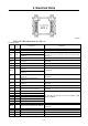
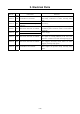
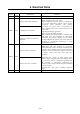
Pin
No.
Line
color
Connection Function
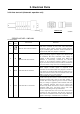
5 Y/W
Remote start/stop switch
(Exterior output terminal plate
through A1 terminal)
Remote start/stop switch connection terminal.
When the remote start/stop switch is switched ON
with No.1 terminal of auto start unit conducted
electrically, XO relay begins to function.
Consequently, the relay is put in order and power is
supplied to PLC unit through ※3 [voltage regulator
(VR1)] and DC-DC converter (DC1).
Further, by function of XO relay, voltage is applied to
PLC unit XO terminal, and the interior contact of Y2
terminal becomes ON (pre-heating operation begins)
and then after 4 seconds the interior contact of Y3
terminal becomes ON (starter motor begins cranking).
Thus engine starts.
When remote start/stop switch is switched OFF, also
XO relay switch becomes OFF. But as electricity is
supplied 5 seconds from PLC unit P3 terminal to PLC
unit itself, the interior contact becomes OFF after
engine cooling down operation continues 5 seconds,
and engine stops.
In case the emergency stop button on operation panel
is pressed, engine stops immediately because the
power for auto start unit No.1 terminal is cut off.
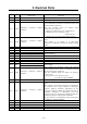
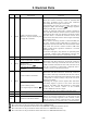
6 - NIL
Starter switch ACC terminal
Charge relay
(Magnetic switch) ※4
7 R/Y
Controller No.8 and No.10
terminal
Power supply for engine start at auto star-up.
When PLC unit XO terminal is electrically conducted
with remote start/stop switch ON, the interior contact
of PLC unit Y2 terminal becomes ON, and auto start
unit No.7 terminal is electrically conducted after 2
seconds to start pre-heating operation.
Starter switch C terminal
8 R/L
Starter (Safety) relay
Start signal input terminal ※5
Output start signal at auto start-up.
When PLC unit XO terminal is electrically conducted
with remote start/stop switch ON, the interior contact
of PLC unit Y3 terminal becomes ON and start signal
is outputted to starter (safety) relay from auto start
unit No.8 terminal.
Regarding the output of start signal, after alternator
generating signal is given to auto start unit No.2
terminal, and PLC unit X2 terminal is electrically
conducted, the interior contact of Y3 terminal
becomes OFF and cuts the output.
Consequently auto start cranking operation stops.
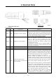
9 B Grounding
T7 - Generator unit T7 terminal
T9 - Generator unit T9 terminal
Detect generating power from generator unit (L1-L3).
Without no electrical conductivity, on X7 relay at auto
start-up and voltage applied to X7 terminal, switch
OFF the interior contact of Y2 and Y3 to stop engine
start function and to cancel the auto re-start function.
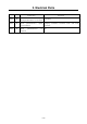
※1:The colours in the parenthesis show those of SDG45S/65S/100S.
※2:The connection in the parenthesis shows that of SDG45S/65S.
※3:The device in the parenthesis shows that only SDG25S is equipped with this device.
※4:The connection in the parenthesis shows that this is for SDG65S/100S only.
※5:The connection in the parenthesis shows that this is for SDG45S/65S/100S only.